

BOSCH REXROTH
0532015125
- BOSCH REXROTH
- Material:0532015125
- Model:0532VAW20/3/FKM/100/D/Z/00/-/-/A1
Due to extremely high demand, please call 877-366-7226 for availability
The Bosch Rexroth 0532VAW20/3/FKM/100/D/Z/00/-/-/A1 Function (0532015125) is a meticulously engineered accumulator shut-off block designed for the secure management of hydraulic accumulators. It provides vital safety and operational functions including protection, isolation, and controlled unloading. The device adheres to the stringent requirements of the Pressure Equipment Directive 2014/68/EU article 4, section 3, ensuring compliance with European safety standards. The shut-off block features a reliable connection to hydraulic accumulators through an accumulator adapter. Its design includes an optional electrically operated 2-way valve which is normally open. This valve facilitates automatic unloading of the accumulator in scenarios such as system shutdowns or activation of emergency off functions, enhancing safety and ease of use. Furthermore, it incorporates a pressure relief valve that guards against excessive pressure build-up that could otherwise compromise system integrity. It is imperative to note that the pressure relief valve within this shut-off block is not intended for control tasks and should be set with a significant margin below the operating pressure to avoid unintended activation. The unit comes ready for connection and offers options for either manual or electromagnetic unloading, depending on user preference or system requirements. Its compact design does not detract from its versatility, offering a broad range of variants to suit various applications. Moreover, the direct-operated pressure relief valve aligns with specifications outlined in data sheet 50153, assuring users of its reliability and performance consistency. The Bosch Rexroth 0532VAW20/3/FKM/100/D/Z/00/-/-/A1 Function (0532015125) represents a sophisticated solution for managing hydraulic accumulator systems effectively while prioritizing safety and operational efficiency.
Function
The accumulator shut-off block serves for the protection, isolation and unloading of hydraulic accumulators. It is classified based on its use according to the Pressure Equipment Directive 2014/68/EU article 4, section 3.
The connection between the accumulator shut-off block and the accumulator is realized by means of an accumulator adapter. An optional, additional, electrically operated 2-way valve (normally open) enables automatic unloading of the accumulator in case of shutdown or "emergency off function". The accumulator is protected from inadmissible overpressure by means of the pressure relief valve.
The pressure relief valve must not be used for any control tasks. Sufficient difference between the pressure set at the pressure relief valve and the operating pressure must be ensured. Response of the pressure relief valve should be prevented.
Ordering code
|
01 |
02 |
03 |
04 |
05 |
06 |
07 |
08 |
09 |
10 |
|||||||||
|
0532VAW |
/ |
/ |
/ |
/ |
/ |
/ |
/ |
/ |
/ |
|
Device designation |
||
|
01 |
Accumulator shut-off block |
0532VAW |
|
Nominal diameter |
||
|
02 |
DN20 |
20 |
|
DN32 |
32 |
|
|
Symbol |
||
|
03 |
Symbol 1 |
1 |
|
Symbol 2 |
2 |
|
|
Symbol 3 |
3 |
|
|
Symbol 4 |
4 |
|
|
Symbol 5 |
51) |
|
|
Symbol 6 |
61) |
|
|
Symbol 7 |
71) |
|
|
Symbol 8 |
8 |
|
|
Symbol 9 |
91) |
|
|
Symbol 10 |
10 |
|
|
Seal material |
||
|
04 |
FKM seal |
FKM |
|
Observe compatibility of seals with hydraulic fluid used. (Other seals upon request) |
||
|
Pressure adjustment |
||
|
05 |
40 bar |
40 |
|
50 bar |
50 |
|
|
70 bar |
70 |
|
|
100 bar |
100 |
|
|
140 bar |
140 |
|
|
160 bar |
160 |
|
|
211 bar |
211 |
|
|
250 bar |
250 |
|
|
280 bar |
280 |
|
|
330 bar |
330 |
|
|
Without pressure relief valve |
‒2) |
|
|
Adjustment type at the pressure relief valve |
||
|
06 |
With hand wheel |
D |
|
Spindle with protective cap |
K |
|
|
Without pressure relief valve |
‒2) |
|
|
Connection thread P |
||
|
07 |
Inch |
Z |
|
Flange |
F1) |
|
|
Unloading |
||
|
08 |
Without directional valve |
003) |
|
2/2 directional valve, manual operation |
014) |
|
|
2/2 directional valve, electrical operation, normally open |
035) |
|
|
Voltage type |
||
|
09 |
Direct voltage 24 V/frequency |
G24/005) |
|
Without directional valve |
‒/‒6) |
|
|
Component series |
||
|
10 |
Component series A with standard version 1 |
A1 |
|
Component series A with special version S |
AS |
|
| 1) | Not possible with version "20" |
| 2) | Only for symbols 1, 2, 5, 8 and 9 |
| 3) | Only for symbols 1, 3 and 6 |
| 4) | Only for symbols 8, 9 and 10 |
| 5) | Only for symbols 2, 4, 5, and 7 |
| 6) | Only for symbols 1, 3, 6, 8, 9 and 10 |
Symbol 1
|
Symbol 2
|
Symbol 3
|
Symbol 4
|
Symbol 8
|
Symbol 10
|
Preferred types DN20
|
Symbol |
Pressure set at the pressure relief valve |
Maximum securable delivery volume |
Denomination |
|
bar |
l/min |
||
|
1 |
‒ |
‒ |
0532VAW20/1/FKM/-/-/Z/00/-/-/A1 |
|
2 |
‒ |
‒ |
0532VAW20/2/FKM/-/-/Z/03/G/24/00/A1 |
|
3 |
50 |
40 |
0532VAW20/3/FKM/050/D/Z/00/-/-/A1 |
|
3 |
70 |
50 |
0532VAW20/3/FKM/070/D/Z/00/-/-/A1 |
|
3 |
100 |
100 |
0532VAW20/3/FKM/100/D/Z/00/-/-/A1 |
|
3 |
140 |
100 |
0532VAW20/3/FKM/140/D/Z/00/-/-/A1 |
|
3 |
160 |
100 |
0532VAW20/3/FKM/160/D/Z/00/-/-/A1 |
|
3 |
211 |
100 |
0532VAW20/3/FKM/211/D/Z/00/-/-/A1 |
|
3 |
250 |
130 |
0532VAW20/3/FKM/250/D/Z/00/-/-/A1 |
|
3 |
280 |
130 |
0532VAW20/3/FKM/280/D/Z/00/-/-/A1 |
|
3 |
330 |
150 |
0532VAW20/3/FKM/330/D/Z/00/-/-/A1 |
|
4 |
70 |
50 |
0532VAW20/4/FKM/070/D/Z/03/G/24/00/A1 |
|
4 |
100 |
100 |
0532VAW20/4/FKM/100/D/Z/03/G/24/00/A1 |
|
4 |
160 |
100 |
0532VAW20/4/FKM/160/D/Z/03/G/24/00/A1 |
|
4 |
211 |
100 |
0532VAW20/4/FKM/211/D/Z/03/G/24/00/A1 |
|
4 |
250 |
130 |
0532VAW20/4/FKM/250/D/Z/03/G/24/00/A1 |
|
4 |
280 |
130 |
0532VAW20/4/FKM/280/D/Z/03/G/24/00/A1 |
|
4 |
330 |
150 |
0532VAW20/4/FKM/330/D/Z/03/G/24/00/A1 |
|
8 |
‒ |
‒ |
0532VAW20/8/FKM/-/-/Z/01/-/-/A1 |
|
10 |
211 |
100 |
0532VAW20/10/FKM/211/K/Z/01/-/-/A1 |
|
10 |
330 |
150 |
0532VAW20/10/FKM/330/K/Z/01/-/-/A1 |
Symbol 1
|
Symbol 2
|
Symbol 3
|
Symbol 4
|
Symbol 5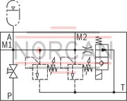
|
Symbol 6
|
Symbol 7
|
Symbol 8
|
Symbol 9
|
Preferred types DN32
|
Symbol |
Pressure set at the pressure relief valve |
Maximum securable delivery volume |
Denomination |
|
bar |
l/min |
||
|
1 |
‒ |
‒ |
0532VAW32/1/FKM/-/-/Z/00/-/-/A1 |
|
2 |
‒ |
‒ |
0532VAW32/2/FKM/-/-/Z/03/G/24/00/A1 |
|
3 |
211 |
100 |
0532VAW32/3/FKM/211/D/Z/00/-/-/A1 |
|
3 |
330 |
150 |
0532VAW32/3/FKM/330/D/Z/00/-/-/A1 |
|
4 |
160 |
100 |
0532VAW32/4/FKM/160/D/Z/03/G/24/00/A1 |
|
4 |
211 |
100 |
0532VAW32/4/FKM/211/D/Z/03/G/24/00/A1 |
|
4 |
330 |
150 |
0532VAW32/4/FKM/330/D/F/03/G/24/00/A1 |
|
4 |
330 |
150 |
0532VAW32/4/FKM/330/D/Z/03/G/24/00/A1 |
|
5 |
‒ |
‒ |
0532VAW32/5/FKM/-/-/Z/03/G/24/00/A1 |
|
7 |
211 |
200 |
0532VAW32/7/FKM/211/DK/F/03/G/24/00/A1 |
|
7 |
250 |
260 |
0532VAW32/7/FKM/250/DK/F/03/G/24/00/A1 |
|
7 |
330 |
300 |
0532VAW32/7/FKM/330/DK/F/03/G/24/00/A1 |
|
8 |
‒ |
‒ |
0532VAW32/8/FKM/-/-/Z/01/-/-/A1 |
|
9 |
‒ |
‒ |
0532VAW32/9/FKM/-/-/F/01/-/-/A1 |
|
9 |
‒ |
‒ |
0532VAW32/9/FKM/-/-/Z/01/-/-/A1 |
general
|
Installation position |
any | |
|
Ambient temperature range |
°C |
-15 … +80 |
hydraulic
|
Maximum operating pressure |
bar |
330 |
|
Hydraulic fluid temperature range |
°C |
-15 … +80 |
|
Seal material |
FKM seals | |
|
Viscosity range |
mm²/s |
12 … 380 |
|
Maximum admissible degree of contamination of the hydraulic fluid, cleanliness class according to ISO 4406 (c) 1) |
Class 20/18/15 | |
| 1) | The cleanliness classes specified for the components must be adhered to in hydraulic systems. Effective filtration prevents faults and simultaneously increases the life cycle of the components. For the selection of the filters, see www.boschrexroth.com/filter. |
|
Hydraulic fluid |
Classification |
Suitable sealing materials |
Standards |
Data sheet |
|
Mineral oil |
HL, HLP |
FKM |
DIN 51524 |
90220 |
|
Other hydraulic fluids on request |
||||
Weight
|
DN20 |
DN32 |
||
|
Symbol |
Weight |
Symbol |
Weight |
|
kg |
kg |
||
| 1 | 4.4 | 1 | 13.8 |
| 2 | 4.7 | 2 | 14.3 |
| 3 | 4.8 | 3 | 15.2 |
| 4 | 5.6 | 4 | 14.7 |
| 5 | - | 5 | 14.2 |
| 7 | - | 7 | 14.4 |
| 8 | 4.6 | 8 | 14.4 |
| 9 | - | 9 | 14.3 |
| 10 | 4.5 | 10 | - |
electrical
|
Voltage type |
Direct voltage | ||
|
Available voltages |
V |
24 | |
|
Protection class according to DIN EN 60529 1) |
With connector "K4" |
IP65 | |
| 1) | With mating connector mounted and locked |
For applications outside these parameters, please consult us!
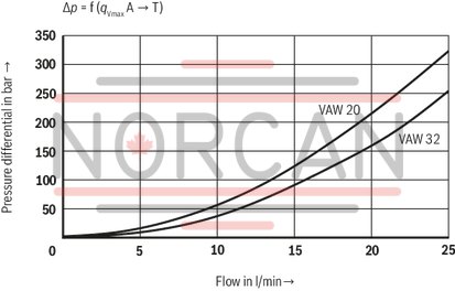
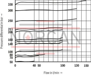
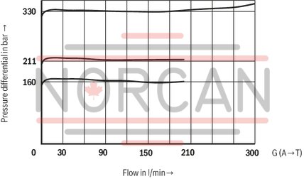
Characteristic curves measured at v = 35 mm2/s, ϑOil = 50 °C
Flow accumulator via unloading valve to the tank
Flow from pump to accumulator

Maximum securable delivery volume of the pressure relief valve
One pressure relief valve
Two pressure relief valves


|
1 |
System shut-off cock |
|
2 |
Pressure relief valve |
|
3 |
Manual unloading |
|
4 |
Electro-magnetic unloading |
|
Connection designation |
|
|
M1, M2 |
Measuring port |
|
P |
Pump connection |
|
A |
Accumulator port |
|
T |
Tank port |
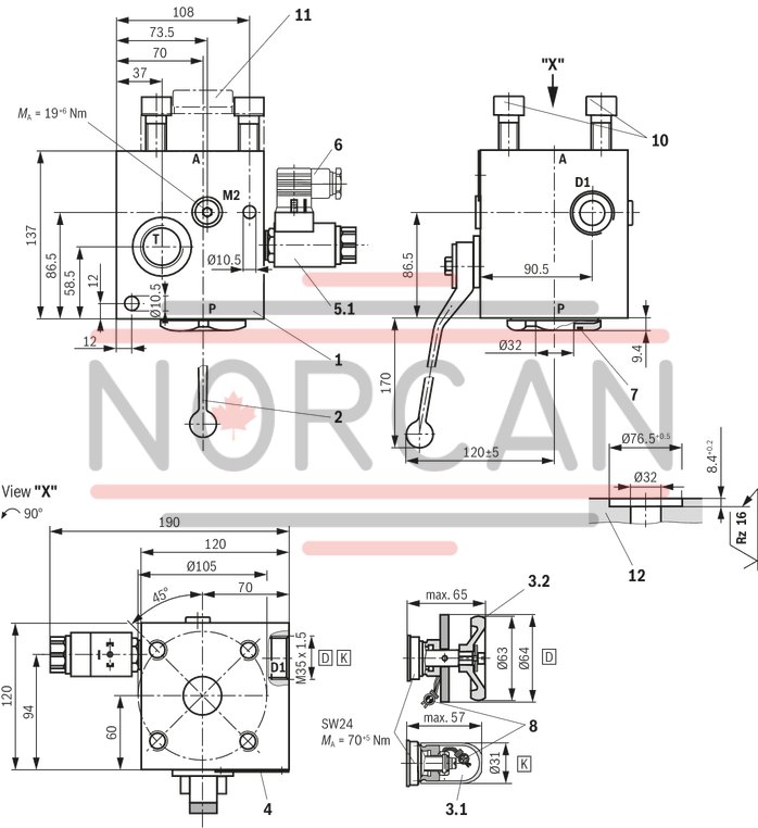
Dimensions: Version "20", symbol 1 and 3
Dimensions in mm

Symbol 1
|
Symbol 3
|
|
Connection thread |
BSP |
|
|
M1 |
Measuring port |
G1/2 |
|
M2 |
Measuring port |
G1/4 |
|
P |
Pump connection |
G1 |
|
T |
Tank port |
G1/2 |
|
A |
Accumulator port |
M33 x 21) |
|
1) Mounting cavity according to DIN EN 9974-1 |
||
Item explanations at the end.
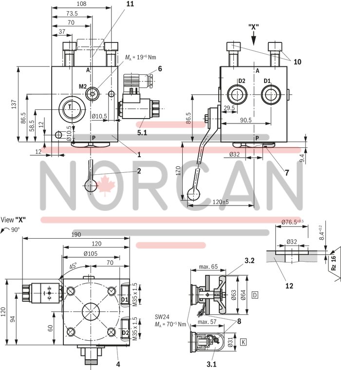
Dimensions: Version "20", symbol 2 and 4
Dimensions in mm

Symbol 2
|
Symbol 4
|
|
Connection thread |
BSP |
|
|
M1 |
Measuring port |
G1/2 |
|
M2 |
Measuring port |
G1/4 |
|
P |
Pump connection |
G1 |
|
T |
Tank port |
G1/2 |
|
A |
Accumulator port |
M33 x 21) |
|
1) Mounting cavity according to DIN EN 9974-1 |
||
Item explanations at the end.
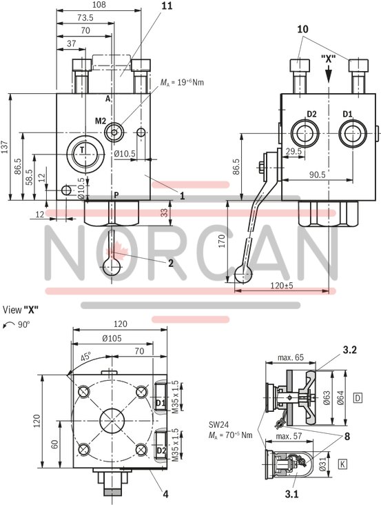
Dimensions: Version "20", symbol 8 and 10
Dimensions in mm

Symbol 8
|
Symbol 10
|
|
Connection thread |
BSP |
|
|
M1 |
Measuring port |
G1/2 |
|
M2 |
Measuring port |
G1/4 |
|
P |
Pump connection |
G1 |
|
T |
Tank port |
G1/2 |
|
A |
Accumulator port |
M33 x 21) |
|
1) Mounting cavity according to DIN EN 9974-1 |
||
Item explanations at the end.
Dimensions: Version "32", symbol 1 and 3
Dimensions in mm

Symbol 1
|
Symbol 3
|
|
Connection thread |
BSP |
|
|
M1 |
Measuring port |
G1/2 |
|
M2 |
Measuring port |
G1/4 |
|
P |
Pump connection |
G1 1/2 |
|
T |
Tank port |
G1 |
|
A |
Accumulator port |
Accumulator adapter, see "Accessories" |
Accumulator adapter separate order, see "Accessories".
Item explanations at the end.
Dimensions: Version "32", symbol 2 and 4
Dimensions in mm

Symbol 2
|
Symbol 4
|
|
Connection thread |
BSP |
|
|
M1 |
Measuring port |
G1/2 |
|
M2 |
Measuring port |
G1/4 |
|
P |
Pump connection |
G1 1/2 |
|
T |
Tank port |
G1 |
|
A |
Accumulator port |
Accumulator adapter, see "Accessories" |
Accumulator adapter separate order, see "Accessories".
Item explanations at the end.
Dimensions: Version "32", symbol 2 and 4
Dimensions in mm
Symbol 2
|
Symbol 4
|
|
Connection thread |
BSP |
|
|
M1 |
Measuring port |
G1/2 |
|
M2 |
Measuring port |
G1/4 |
|
P |
Pump connection (flange) |
TK = Ø98 mm 4 x M16 |
|
T |
Tank port |
G1 |
|
A |
Accumulator port |
Accumulator adapter, see "Accessories" |
Accumulator adapter separate order, see "Accessories".
Item explanations at the end.
Dimensions: Version "32", symbol 5 and 7
Dimensions in mm

Symbol 5
|
Symbol 7
|
|
Connection thread |
BSP |
|
|
M1 |
Measuring port |
G1/2 |
|
M2 |
Measuring port |
G1/4 |
|
P |
Pump connection |
G1 1/2 |
|
T |
Tank port |
G1 |
|
A |
Accumulator port |
Accumulator adapter, see "Accessories" |
Accumulator adapter separate order, see "Accessories".
Item explanations at the end.
Dimensions: Version "32", symbol 5 and 7
Dimensions in mm
Symbol 5
|
Symbol 7
|
|
Connection thread |
BSP |
|
|
M1 |
Measuring port |
G1/2 |
|
M2 |
Measuring port |
G1/4 |
|
P |
Pump connection (flange) |
TK = Ø98 mm 4 x M16 |
|
T |
Tank port |
G1 |
|
A |
Accumulator port |
Accumulator adapter, see "Accessories" |
Accumulator adapter separate order, see "Accessories".
Item explanations at the end.
Dimensions: Version "32", symbol 6
Dimensions in mm
Symbol 6
|
|
Connection thread |
BSP |
|
|
M1 |
Measuring port |
G1/2 |
|
M2 |
Measuring port |
G1/4 |
|
P |
Pump connection |
G1 1/2 |
|
T |
Tank port |
G1 |
|
A |
Accumulator port |
Accumulator adapter, see "Accessories" |
Accumulator adapter separate order, see "Accessories".
Item explanations at the end.
Dimensions: Version "32", symbol 8
Dimensions in mm

Symbol 8
|
|
Connection thread |
BSP |
|
|
M1 |
Measuring port |
G1/2 |
|
M2 |
Measuring port |
G1/4 |
|
P |
Pump connection |
G1 1/2 |
|
T |
Tank port |
G1 |
|
A |
Accumulator port |
Accumulator adapter, see "Accessories" |
Accumulator adapter separate order, see "Accessories".
Item explanations at the end.
Dimensions: Version "32", symbol 9
Dimensions in mm

Symbol 9
|
|
Connection thread |
BSP |
|
|
M1 |
Measuring port |
G1/2 |
|
M2 |
Measuring port |
G1/4 |
|
P |
Pump connection |
G1 1/2 |
|
T |
Tank port |
G1 |
|
A |
Accumulator port |
Accumulator adapter, see "Accessories" |
Accumulator adapter separate order, see "Accessories".
Item explanations at the end.
Dimensions: Item explanations
|
1 |
Block |
|
2 |
System shut-off cock |
|
3.1 |
Pressure relief valve, adjustment type "K" with spindle and protective cap; sealed |
|
3.2 |
Pressure relief valve, adjustment type "D" with hand wheel and manual unloading; sealed |
|
4 |
Name plate |
|
5.1 |
Electro-magnetic unloading |
|
5.2 |
Manual unloading, closed |
|
6 |
Mating connector included in the scope of delivery |
|
7 |
Seal ring Ø40 x 3 |
|
8 |
Sealing |
|
9 |
Space required to remove the connector |
|
10 |
Hexagon socket head cap screws 4 pieces ISO 4762 - M16 x 45 - 10 Tightening torque MA = 250+10 Nm |
|
11 |
Accumulator adapter, see "Accessories" |
|
12 |
Counterflange for port P (separate order) |
Accumulator adapter BSP thread
Accumulator adapter for version "32", maximum operating pressure 330 bar
Type: S307V/G1 1/4-DN32 and S309V/G2-DN32
Dimensions in mm
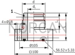
|
Short designation |
Accumulator adapter |
Part number |
d |
d1 |
L |
L1 |
Seal ring |
|
mm |
mm |
mm |
mm |
||||
|
S307 - - |
S307V/G1 1/4-DN32 | R900085303 | G1 1/4 | 20 | 67 | 37 | 30 x 3 |
|
S309 - - |
S309 S309V/G2-DN32 | R900545858 | G2 | 32 | 73 | 43 | 48 x 3 |
|
Pressure set at the pressure relief valve |
Adjustment type at the pressure relief valve |
Maximum securable delivery volume |
Part number |
|
|
bar |
Hand wheel |
Spindle with protective cap |
l/min |
FKM |
|
50 |

|
40 |
0532004200 |
|
|
70 |
50 |
0532004201 |
||
|
100 |
100 |
0532004202 |
||
|
120 |
100 |
0532004211 |
||
|
140 |
100 |
0532004203 |
||
|
160 |
100 |
0532004204 |
||
|
200 |
100 |
0532004209 |
||
|
211 |
100 |
0532004205 |
||
|
250 |
130 |
0532004206 |
||
|
280 |
130 |
0532004210 |
||
|
300 |
130 |
0532004207 |
||
|
330 |
150 |
0532004208 |
||
|
50 |

|
40 |
0532004102 |
|
|
70 |
50 |
0532004103 |
||
|
80 |
60 |
0532004111 |
||
|
100 |
100 |
0532004104 |
||
|
120 |
100 |
0532004114 |
||
|
140 |
100 |
0532004107 |
||
|
160 |
100 |
0532004105 |
||
|
180 |
100 |
0532004113 |
||
|
200 |
100 |
0532004110 |
||
|
211 |
100 |
0532004100 |
||
|
250 |
130 |
0532004106 |
||
|
260 |
130 |
0532004115 |
||
|
280 |
130 |
0532004112 |
||
|
300 |
130 |
0532004101 |
||
|
330 |
150 |
0532004108 |
||
Type-examination tested safety valves type 0532VA according to Pressure Equipment Directive 2014/68/EU
Before ordering a type-examination tested safety valve, it must be observed that for the desired response pressure p, the maximum admissible flow qVmax of the safety valve must be larger than the maximum possible flow of the system/accumulator to be secured. In this respect, the applicable regulations must be observed! According to the Pressure Equipment Directive 2014/68/EU, the increase in the system pressure due to the flow must not exceed 10 % of the set response pressure (see component marking). The maximum admissible flow qVmax stated in the component marking must not be exceeded. Discharge lines of safety valves must end in a risk-free manner. Accumulation of fluids in the discharge system must not be possible (see AD2000 - data sheet A2).
Always observe application notes!
The response pressure specified in the component marking is set in the plant. The maximum admissible flow stated in the component marking applies for applications without counter pressure in the discharge line (port T). By removing the lead seal at the safety valve, the approval according to the Pressure Equipment Directive becomes void! The requirements of the Pressure Equipment Directive and of data sheet AD2000 A2 must be generally observed! It is recommended to secure type-examination tested safety valves against inadmissible removal from the screw-in housing/block by means of wiring and sealing with the housing/block (bore available in the adjustment element).
Notice:
The system pressure increases by the counter pressure in the discharge line (port T) due to the increasing flow. (Observe the data sheet AD2000 A2, point 6.3!) To ensure that this increase in system pressure caused by the flow does not exceed the value of 10% of the set response pressure, the admissible flow has to be reduced dependent on the counter pressure in the discharge line (port T) (see diagrams/characteristic curves).