

BOSCH REXROTH
0811104116
$946.50 USD
- BOSCH REXROTH
- Material:0811104116
- Model:ZDBT-XP3-1X/160
Quantity in stock: 0
The Bosch Rexroth ZDBT-XP3-1X/160 (0811104116) is a precision-engineered pressure relief valve designed for effective system pressure limitation in hydraulic systems. This remote control valve features a seat design and is primarily used to maintain the desired pressure within a hydraulic circuit by limiting the system pressure. It operates manually through an adjustment mechanism, allowing for precise user control over the pressure settings. The construction of this valve includes a robust housing, a responsive valve poppet, and a corresponding valve seat, ensuring reliable operation and durability. In its default state, the valve poppet is seated firmly against the valve seat, creating a seal that prevents fluid flow between the P (pressure inlet) and T (tank) connections. The system's hydraulic force acts against this seal; when it reaches the force preset by the adjustment mechanism, the valve activates to regulate pressure. Upon reaching the set threshold, the ZDBT-XP3-1X/160 allows excess fluid to bypass from P to T by lifting off the poppet from its seat. This action enables it to maintain system stability by relieving excess pressure in a controlled manner. Additionally, when there is no load on its spring, there is a minimum guaranteed pressure of 3 bar due to spring preload force. This model is specifically intended for use as a pilot control valve in applications requiring indirect control of large fluid flows. Its design facilitates installation on subplates or within control panels, making it versatile for various hydraulic system configurations. The ZDBT-XP3-1X/160 exemplifies high-quality engineering suitable for precise control in complex hydraulic systems.
Pressure relief valves of type DBT are remote control valves with seat design and are used for limiting a system pressure.
The setting is completed manually, via the adjustment type (4).
The valves basically consist of the housing (1), the valve poppet (2) and the related valve seat (3).
In the unloaded position, the valve poppet (2) pushes onto the valve seat (3) and blocks the connection between P and T connection.
If the hydraulic force equals the force set at the adjustment type (4), the valve controls the set pressure.
By lifting off the valve poppet (2) from the valve seat (3), the excessive hydraulic fluid may flow off from P to T.
With completely unloaded spring (5), the minimum pressure of 3 bar (spring preload force) will settle.
These valves are basically used as pilot control valves for the indirect control of larger flows.
Type DBT-XP2-1X

Ordering code, symbols
|
Type |
Part number |
Examples of application |
Symbols |
|
DBT–G1–1X/160 |
0 811 104 007 |
For control panel
|

|
|
DBT–G1–1X/315 |
0 811 104 013 |
||
|
DBT–G7–1X/160 |
0 811 104 021 |
||
|
DBT–XP8–1X/160 |
0 811 104 100 |
Sandwich plate for subplate mounting
|
|
|
DBT–XP8–1X/315 |
0 811 104 101 |
||
|
DBT–XP2–1X/160 |
0 811 104 102 |
||
|
DBT–XP2–1X/315 |
0 811 104 103 |
||
|
DBT–XP7–1X/160 |
0 811 104 104 |
||
|
DBT–XP7–1X/315 |
0 811 104 105 |
||
|
DBT–XP3–1X/160 |
0 811 104 106 |
||
|
DBT–XP3–1X/315 |
0 811 104 107 |
||
|
DBT–XP1–1X/160 |
0 811 104 108 |
||
|
DBT–XP1–1X/315 |
0 811 104 109 |
||
|
ZDBT–XP8–1X/160 |
0 811 104 110 |
Sandwich plate for subplate mounting
|
|
|
ZDBT–XP8–1X/315 |
0 811 104 111 |
||
|
ZDBT–XP2–1X/160 |
0 811 104 112 |
||
|
ZDBT–XP2–1X/315 |
0 811 104 113 |
||
|
ZDBT–XP7–1X/160 |
0 811 104 114 |
||
|
ZDBT–XP7–1X/315 |
0 811 104 115 |
||
|
ZDBT–XP3–1X/160 |
0 811 104 116 |
||
|
ZDBT–XP3–1X/315 |
0 811 104 117 |
||
|
ZDBT–XA8–1X/160 |
0 811 104 118 |
For subplate mounting
|

|
|
ZDBT–XA8–1X/315 |
0 811 104 119 |
||
|
ZDBT–XA2–1X/160 |
0 811 104 120 |
||
|
ZDBT–XA2–1X/315 |
0 811 104 121 |
||
|
DZT–XB2–1X/315 |
0 811 104 123 |
Pressure switch valve for subplate mounting
|

|
|
DZT–XB2–1X/60 |
0 811 104 124 |
||
|
DZT–XA2–1X/60 |
0 811 104 125 |

|
|
|
DZT–XA2–1X/160 |
0 811 104 126 |
||
|
DZT–XA2–1X/315 |
0 811 104 127 |
general
|
Size |
6 | |
|
Weight |
kg |
2 |
|
Installation position |
any | |
|
Ambient temperature range |
°C |
-20 … +70 |
|
Storage temperature range |
°C |
-20 … +80 |
hydraulic (measured with HLP 46; ϑ Oil = 40 °C ±5 °C, ν = 35 mm2/s)
|
Size |
6 | ||
|
Maximum operating pressure |
Port P |
bar |
350 |
|
Maximum set pressure |
Pressure rating 60 bar 1) |
bar |
60 |
|
Pressure rating 16 bar |
bar |
160 | |
|
Pressure rating 315 bar |
bar |
315 | |
|
Pressure rating 350 bar |
bar |
350 | |
|
Minimum set pressure |
bar |
3 | |
|
Return flow |
Port T |
separate and depressurized to the tank | |
|
Maximum flow |
l/min |
3 | |
|
Hydraulic fluid |
Mineral oil (HL, HLP) according to DIN 51524, other hydraulic fluids on request | ||
|
Hydraulic fluid temperature range |
°C |
-20 … +80 | |
|
Viscosity range |
mm²/s |
15 … 380 | |
|
Maximum admissible degree of contamination of the hydraulic fluid 2) |
Class 20/18/15 according to ISO 4406 (c) | ||
|
Hysteresis (deviation from the max. set pressure) |
% |
< 5 | |
|
Pilot oil volume (Vx) (only pressure switch valves) |
cm³ |
0.5 | |
| 1) | only possible with type DZT |
| 2) | The cleanliness classes specified for the components must be adhered to in hydraulic systems. Effective filtration prevents faults and simultaneously increases the life cycle of the components. For the selection of the filters, see www.boschrexroth.com/filter. |
For applications outside these parameters, please consult us!
Δp = f (qV)

(measured with HLP46, ϑOil = 40 ±5 °C), ν = 35 mm2/s)
Type DBT-G1-1X/...
Dimensions in mm
|
1 |
Hand wheel |
|
2 |
Rotary knob |
|
3 |
Valve mounting bores |
|
4 |
Pressure gauge connection |
|
5 |
Lock nut |
Valve mounting screws (separate order)
4 hexagon socket head cap screws M6,
screw length as required
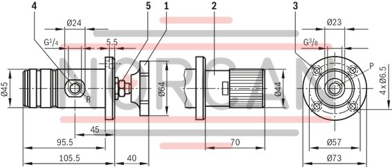
Type DBT-X... Type ZDBT-X...
Dimensions in mm

|
1 |
Name plate or 2nd flange surface |
|
2 |
Adjustment type |
|
3 |
Lock nut |
|
4 |
Valve mounting bores |
|
5 |
O-rings Ø9.25 x 1.78 mm (ports P, T) |
|
6 |
Machined valve contact surface; Porting pattern according to ISO 4401-03-02-0-05 Subplates see data sheet 45052 |
Valve mounting screws (separate order)
type DBT4 hexagon socket head cap screws ISO 4762-M5x50-10.9-flZn-240h-L
(friction coefficient μtotal = 0.09 – 0.14);
tightening torque MA = 7 Nm ±10 %
or
4 hexagon socket head cap screws ISO 4762-M5x50-10.9
(friction coefficient μtotal = 0.12 – 0.17);
tightening torque MA = 8.9 Nm ± 10%
type ZDBT4 hexagon socket head cap screws ISO 4762-M5-10.9-flZn-240h-L
(friction coefficient μtotal = 0.09 – 0.14);
tightening torque MA = 7 Nm ±10 %
or
4 hexagon socket head cap screws ISO 4762-M5-10.9
(friction coefficient μtotal = 0.12 – 0.17);
tightening torque MA = 8.9 Nm ± 10%
Screw length as required
Type DZT-X...
Dimensions in mm

|
1 |
Name plate |
|
2 |
Adjustment element |
|
3 |
Lock nut |
|
4 |
Valve mounting bores |
|
5 |
Pressure gauge connection for pilot pressure X, G1/4 |
|
6 |
Pressure gauge connection for system pressure A, G1/4 |
|
7 |
O-rings Ø10 x 1.5 mm (ports P, A, B, T) |
|
8 |
Machined valve contact surface; Porting pattern according to ISO 4401-03-02-0-05 Subplates see data sheet 45052 |
Valve mounting screws (separate order)
4 hexagon socket head cap screws ISO 4762-M5x50-10.9-flZn-240h-L
(friction coefficient μtotal = 0.09 –0,14);
tightening torque MA = 7 Nm ± 10%
or
4 hexagon socket head cap screws ISO 4762-M5x50-10.9
(friction coefficient μtotal = 0.12 – 0.17);
tightening torque MA = 8.9 Nm ± 10%
Screw length as required
Examples of application
