
BOSCH REXROTH
0811404036
$4,623.91 USD
- BOSCH REXROTH
- Material:0811404036
- Model:4WRPH6C3B40L-2X/G24Z4/M
Quantity in stock: 0
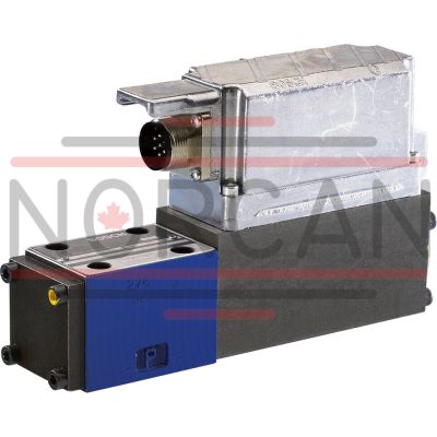
The Bosch Rexroth 4WRPH6C3B40L-2X/G24Z4/M (0811404036) is a high-response industrial hydraulic valve designed for precise control of oil flow direction in electro-hydraulic systems. This size 6 valve, with symbol C3, features an external amplifier and operates on a 24 V DC power supply. It provides reliable and rapid response thanks to its direct actuation and the use of an external piston position feedback mechanism, which ensures high accuracy. The 4WRPH6 series valves are direct operated valves that deliver servo quality performance. They are uniquely designed to be actuated from one side and maintain a default 4/4 fail-safe position when deactivated. This characteristic makes them particularly suitable for safety-critical applications where it is essential that the valve returns to a safe state in the event of power loss. These valves incorporate a control spool and sleeve that meet servo quality standards, ensuring smooth and precise operation. The control solenoid comes equipped with electrical position feedback, along with electronics for the position transducer (Lvdt DC/DC), which further enhances the valve's responsiveness and accuracy. Specifically engineered for subplate mounting, the Bosch 4WRPH6C3B40L-2X/G24Z4/M conforms to the porting pattern set by ISO 4401 standards, facilitating easy installation and compatibility with various hydraulic systems. Its robust design makes it an ideal component for use in sophisticated electro-hydraulic controls within both production environments and test systems where high performance and reliability are paramount.
Size 6, symbol C3, external amplifier, 24 V DC
Industrial hydraulic valve in a high performance range. Reliable and quick control of the direction of the oil flow according to hydraulic symbol. High accuracy thanks to external piston position feedback.
Unpacked Weight: 2.7 kg
Valves of type 4WRPH6 are direct operated high-response valve in servo quality with electric position feedback. The valves are actuated on one side and in their deactivated condition take a 4/4 fail-safe position. They are suitable for electro-hydraulic controls in production and test systems.
| Spool valve |
| Direct actuated |
| Data Sheet | Download Data Sheet |
| 3D CAD | Download 3D CAD |
| Manual | Download Manual |
| Manual | Download Manual |
| Manual | Download Manual |
| Manual | Download Manual |
| Manual | Download Manual |
| Spool symbol | Symbol C3 |
| Max. pressure | 315 |
| Electrical connection description | Connector 3-pole (2 + PE) according to EN 175301-803 |
| Productgroup ID | 9,10,11,12,13,14 |
| Number of ports | 4 |
| Type of actuation | Electrical with external electronics |
| Size | 6 |
| Electrical connector | Connector 3-pole (2 + PE) |
| Max. flow | 50 |
| Type of connection | Subplate mounting |
| Connection diagram NFPA | NFPA T3.5.1 R2-2002 D05 |
| Size_CETOP | D05 |
| Nominal flow | 40 |
| Connection diagram | ISO 4401-03-02-0-94 |
| Supply voltage | 24 VDC |
| Number of switching positions | 4 |
| Weight | 2.7 |
| Seals | NBR |
| Hydraulic fluid | HL,HLP,HLPD,HVLP,HVLPD,HFC |
| Conformity | CE,RoHS |
|
01 |
02 |
03 |
04 |
05 |
06 |
07 |
08 |
09 |
10 |
11 |
12 |
13 |
|||
|
4 |
WRP |
H |
6 |
B |
‒ |
2X |
/ |
G24 |
Z4 |
/ |
M |
* |
|
01 |
4 main ports |
4 |
|
02 |
High-response directional valve, direct operated |
WRP |
|
03 |
Control spool/sleeve |
H |
|
04 |
Size 6 |
6 |
|
05 |
Symbols; for the possible version, see "Symbols/Circuit diagrams" |
C1, C3, C4, C5 |
|
Installation side of the inductive position transducer |
||
|
06 |
Valve side B (standard) (see "Symbols/Circuit diagrams") |
B |
|
Rated flow at 70 bar valve pressure differential (35 bar/control edge) |
||
|
07 |
2 l/min |
02 |
|
4 l/min |
04 |
|
|
12 l/min |
12 |
|
|
15 l/min |
15 1) |
|
|
24 l/min |
24 |
|
|
25 l/min |
25 1) |
|
|
40 l/min |
40 3) |
|
|
Flow characteristic |
||
|
08 |
Linear |
L |
|
Inflected characteristic curve |
P 2) |
|
|
09 |
Component series 20 ... 29 (20 ... 29: unchanged installation and connection dimensions) - Size 6 |
2X |
|
Supply voltage of the control electronics |
||
|
10 |
Direct voltage 24 V |
G24 |
|
Electrical connection |
||
|
11 |
With connector according to DIN 43560-AM2, mating connector included in the scope of delivery |
Z4 |
|
Seal material |
||
|
12 |
NBR seals |
M |
|
13 |
Further details in the plain text |
* |
|
1) |
Only available with flow characteristics P |
|
|
2) |
Inflection 60 % for NG6 with rated flows "15" and "25", otherwise inflection 40 % |
|
|
3) |
qv 2:1 only with rated flow = 40 l/min |
|
For applications outside these parameters, please consult us!
general
|
Type |
4WRPH | |
|
Size |
6 | |
|
Component series |
2X | |
|
Type of actuation |
Proportional solenoid with position control, electrical amplifier external | |
|
Type of connection |
For subplate mounting: Porting pattern according to ISO 4401 | |
|
Installation position |
Any | |
|
Weight |
kg |
2.3 |
|
Ambient temperature range |
°C |
-20 … +50 |
hydraulic
|
Type |
4WRPH | ||
|
Size |
6 | ||
|
Maximum operating pressure |
bar |
315 | |
|
Maximum operating pressure |
Port P |
bar |
315 |
|
Port A |
bar |
315 | |
|
Port B |
bar |
315 | |
|
Port T |
bar |
250 | |
|
Maximum flow |
l/min |
40 | |
|
Nominal flow |
l/min |
2 4 12 15 24 40 |
|
|
Hydraulic fluid temperature range |
°C |
-20 … +80 | |
|
Viscosity range |
Maximum admissible |
mm²/s |
10 … 800 |
|
Recommended |
mm²/s |
20 … 100 | |
|
Maximum admissible degree of contamination of the hydraulic fluid, cleanliness class according to ISO 4406 (c) 1) |
Class 18/16/13 according to ISO 4406 (c) | ||
|
Hysteresis |
% |
≤ 0.2 | |
|
Manufacturing tolerance |
% |
< 10 | |
| 1) | The cleanliness classes specified for the components must be adhered to in hydraulic systems. Effective filtration prevents faults and simultaneously increases the life cycle of the components. For the selection of the filters, see www.boschrexroth.com/filter. |
hydraulic
|
Nominal flow 1) |
l/min |
2 | 4 | 12 | 15 | 24 | 40 | |
|
Limitation of use |
Symbols C, C3, C5 |
bar |
315 | 160 | ||||
|
Symbols C1, C4 |
bar |
315 | 280 | 250 | 100 | |||
|
Leakage flow (at 100 bar) |
Linear characteristic curve “L” |
l/min |
< 150 | < 180 | < 300 | - | < 500 | < 900 |
|
Inflected characteristic curve "P" |
l/min |
- | < 180 | < 300 | < 450 | |||
| 1) | With Δp = 35 bar/control edge |
electrical
|
Type |
4WRPH | ||
|
Size |
6 | ||
|
Power supply |
Nominal voltage |
V |
24 |
|
Maximum solenoid current |
A |
2.7 | |
|
Coil resistance with solenoid temperature 20 °C |
Ω |
2.5 | |
|
Duty cycle |
% |
100 | |
|
Maximum power consumption |
VA |
40 | |