

BOSCH REXROTH
0811404290
$14,586.49 USD
- BOSCH REXROTH
- Material:0811404290
- Model:4WRVE16V120M-2X/G24K0/B5M
Quantity in stock: 0
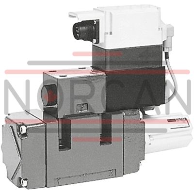
The Bosch Rexroth 4WRVE16V120M-2X/G24K0/B5M (0811404290) is a state-of-the-art industrial hydraulic valve designed for high-performance applications requiring reliable and precise control of oil flow direction. This valve is characterized by its size 16 and symbol V, denoting its specific configuration and capabilities within the Bosch product line. The integrated electronics feature 24V DC power supply, which includes an onboard electronics (OBE) with a position controller for both pilot and main stages, ensuring calibrated control right from the plant. The 4WRVE model is a pilot-operated 4/3 high-response directional valve that boasts a spool and sleeve of servo quality, providing users with exceptional responsiveness and control precision. The main stage of the valve also comes in servo quality and includes position feedback, which contributes to its high accuracy in operation. The flow characteristics of this model are designated by an 'M,' indicating a progressive and fine control edge that enables smooth modulation of flow. This particular valve is well-suited for applications where quick response times and exacting control of hydraulic systems are essential. Its pilot-operated nature ensures that even at low power levels, the valve can effectively manage large flows with great efficiency. The linear flow characteristic option 'L' can be chosen for applications requiring a direct proportion between the valve input signal and the output flow. Overall, the Bosch 4WRVE16V120M-2X/G24K0/B5M (0811404290) represents a sophisticated solution for industries that demand rigorous control over their hydraulic systems with minimal deviation or error in performance. Its robust design, coupled with advanced electronic controls, makes it an indispensable component in various high-demand hydraulic scenarios.
Size 16, symbol V, integrated electronics, 24 V DC
Industrial hydraulic valve in a high performance range. Reliable and quick control of the direction of the oil flow according to hydraulic symbol. High accuracy thanks to internal piston position feedback
Unpacked Weight: 11.008 kg
Valves of type 4WRVE are pilot-operated high-response valves in servo quality.
| External pilot oil supply, external pilot oil return |
| Spool valve |
| Pilot-operated |
| Progressive with linear fine control range |
| Rated flow 40 … 430 l/min |
| Component series 2X |
| Maximum operating pressure 350 bar |
| Size 10 … 27 |
| Maximum flow 1000 l/min |
| Data Sheet | Download Data Sheet |
| Manual | Download Manual |
| Manual | Download Manual |
| Manual | Download Manual |
| Manual | Download Manual |
| Manual | Download Manual |
| Spool symbol | Symbol V |
| Max. pressure | 350 |
| Electrical connection description | Connector 12-pole (11 + PE) according to EN 175201-804 |
| Productgroup ID | 9,10,11,12,13,14 |
| Number of ports | 4 |
| Type of actuation | Electrical with integrated electronics |
| Size | 16 |
| Max. flow | 450 |
| Type of connection | Subplate mounting |
| Connection diagram NFPA | NFPA T3.5.1 R2-2002 D07 |
| Size_CETOP | D07 |
| Nominal flow | 120 |
| Connection diagram | ISO 4401-07-07-0-05 |
| Supply voltage | 24 VDC |
| Number of switching positions | 3 |
| Weight | 11.008 |
| Seals | NBR |
| Connectivity | Analog, command value 0 … 10 V |
| Hydraulic fluid | HL,HLP |
| Hydraulic fluid | HL,HLP,HLPD,HVLP,HVLPD,HFC |
|
01 |
02 |
03 |
04 |
05 |
06 |
07 |
08 |
09 |
10 |
11 |
12 |
13 |
14 |
|||
|
4 |
WRV |
E |
‒ |
2X |
/ |
G24 |
K0 |
/ |
B5 |
M |
* |
|
01 |
4 main ports |
4 |
|
02 |
High-response directional valve, pilot operated |
WRV |
|
03 |
With integrated electronics (OBE) |
E |
|
04 |
Size 10 |
10 |
|
Size 16 |
16 |
|
|
Size 25 |
25 |
|
|
Size 27 |
27 1) |
|
|
05 |
Symbols; for the possible version, see "Symbols/Circuit diagrams" |
V, V1 |
|
Rated flow (Δp = 5 bar) |
||
|
06 |
Size 10 |
|
|
40 l/min |
40 2) |
|
|
55 l/min |
55 3) |
|
|
70 l/min |
70 2) |
|
|
85 l/min |
85 3) |
|
|
Size 16 |
||
|
90 l/min |
90 2) |
|
|
120 l/min |
120 3) |
|
|
150 l/min |
150 2) |
|
|
200 l/min |
200 3) |
|
|
Size 25 |
||
|
300 l/min |
300 2) |
|
|
370 l/min |
370 3) |
|
|
Size 27 |
||
|
430 l/min |
430 1) 3) |
|
|
Flow characteristic |
||
|
07 |
Progressive with linear fine control range |
M |
|
Inflected characteristic curve, linear (inflection at 40 %) |
P |
|
|
Linear |
L |
|
|
08 |
Component series 20 ... 29 (20 ... 29: unchanged installation and connection dimensions) - Size 6 |
2X |
|
Supply voltage of the control electronics |
||
|
09 |
Direct voltage 24 V |
G24 |
|
Pilot oil supply and return |
||
|
10 |
External pilot oil supply, external pilot oil return |
no code |
|
Internal pilot oil supply, external pilot oil return |
E |
|
|
Pilot oil supply internal, pilot oil return internal |
ET |
|
|
External pilot oil supply, internal pilot oil return |
T |
|
|
Electrical connection |
||
|
11 |
Without mating connector; connector DIN 43563-AM6 |
K0 |
|
Electrical interface |
||
|
12 |
Command value ±10 V |
B5 |
|
Seal material |
||
|
13 |
NBR seals |
M |
|
14 |
Further details in the plain text |
* |
|
1) |
NG27 is a high-flow version of NG25, the connection bores P, A, B, T in the main stage are designed with Ø32 mm. Deviating from the standard ISO 4401-08-08-0-05, ports P, A, B, T can be bored in the manifold with a maximum of Ø30 mm. So these valves offer higher flow values QA : QB |
|
|
2) |
QN: flow characteristic P |
|
|
3) |
QN: flow characteristic M or L |
|
For applications outside these parameters, please consult us!
general
|
Type |
4WRVE | ||||
|
Size |
10 | 16 | 25 | 27 | |
|
Component series |
2X | ||||
|
Design |
Directional spool valve, pilot-operated | ||||
|
Type of actuation |
High-response directional valve NG6 with position control for pilot control and main valve | ||||
|
Anschlussart |
For subplate mounting: Porting pattern according to ISO 4401 | ||||
|
Installation position |
Any | ||||
|
Earth |
kg |
8 | 10.4 | 18.2 | |
|
Ambient temperature range |
°C |
-20 … +50 | |||
hydraulic
|
Type |
4WRVE | ||||||
|
Size |
10 | 16 | 25 | 27 | |||
|
Maximum operating pressure |
bar |
350 | |||||
|
Maximum operating pressure |
Port T |
bar |
250 | ||||
|
Port Y |
bar |
250 | |||||
|
Port X |
bar |
250 | |||||
|
Maximum operating pressure |
Port P |
External pilot oil supply |
bar |
350 | |||
|
Port A |
bar |
350 | |||||
|
Port B |
bar |
350 | |||||
|
Maximum operating pressure |
Port P |
Internal pilot oil supply |
bar |
250 | |||
|
Port A |
bar |
250 | |||||
|
Port B |
bar |
250 | |||||
|
Nominal flow 1) |
l/min |
40 55 70 85 |
90 120 150 200 |
300 370 |
430 | ||
|
Nominal flow |
Pilot control valve |
l/min |
8 | 24 | 40 | ||
|
Maximum flow |
l/min |
170 | 450 | 900 | 1000 | ||
|
Hydraulic fluid temperature range |
°C |
-20 … +65 | |||||
|
Viscosity range |
mm²/s |
10 … 800 | |||||
|
preferably |
mm²/s |
20 … 100 | |||||
|
Maximum admissible degree of contamination of the hydraulic fluid, cleanliness class according to ISO 4406 (c) 2) |
Class 18/16/13 according to ISO 4406 (c) | ||||||
|
Hysteresis |
% |
< 0.1 | |||||
|
Manufacturing tolerance |
% |
≤ 10 | |||||
|
Temperature drift |
% |
< 1 | |||||
|
Actuating time |
0 ... 100 % |
ms |
12 | 15 | 23 | ||
|
0 ... 10 % |
ms |
6 | 7 | 10 | |||
|
Actuating time |
0 ... 100 % |
Symbol E, E1-, W6-, W8- |
ms |
40 | 50 | 90 | |
| 1) | Δp = 5 bar per edge |
| 2) | The cleanliness classes specified for the components must be adhered to in hydraulic systems. Effective filtration prevents faults and simultaneously increases the life cycle of the components. For the selection of the filters, see www.boschrexroth.com/filter. |
electrical
|
Type |
4WRVE | ||
|
Power supply |
Nominal voltage |
V |
24 |
|
Lower limit value |
V |
21 | |
|
Upper limit value |
V |
40 | |
|
Duty cycle |
% |
100 | |
|
Maximum power consumption |
VA |
30 | |
|
Required fuse protection |
AT |
2.5 AF | |
|
Protection class according to DIN EN 60529 |
IP65 (with mating connector mounted and locked) | ||
|
EMC (electro-magnetic compatibility) |
CE conformity according to EMC directive 2004/108/EC tested according to EN 61000-6-2 and EN 61000-6-3 | ||
|
Zero point calibration 1) |
% |
± 1 | |
| 1) | ex works |