


BOSCH REXROTH
0811404827
- BOSCH REXROTH
- Material:0811404827
- Model:4WRPEH10C5B100P-2X/G24K0/A1M
Quantity in stock: 0
The Bosch Rexroth 4WRPEH10C5B100P-2X/G24K0/A1M (0811404827) is a high-response directional valve designed for precise control in electro-hydraulic systems. It is a direct-operated valve with a control spool and sleeve in servo quality, ensuring reliable and accurate operation. The valve features integrated electronics that compare the specified command value with the position actual value to adjust the stroke solenoid accordingly, modulating the control spool against the spring based on control deviations. This model includes an electric position feedback mechanism and factory-calibrated integrated electronics (OBE), which contribute to its precise functioning. The electrical connection is a 6P+PE type, and it accepts signal input through either an "A1" interface with ±10 V or an "F1" interface for 4 ... 20 mA signals (with Rsh = 200 Ω). Its design facilitates use in production and test systems that require electro-hydraulic controls. The valve operates on one side and ensures a 4/4 fail-safe position when switched off, immediately moving to a secured basic position for safety. This switch-off behavior includes passing through positions P–B/A–T, which may cause movements in the controlled component and should be considered during system design. The product consists of three main components: the control solenoid with a position transducer, the valve body, and the mating connector. This Bosch directional valve is suitable for applications requiring precise movement control and quick response times, such as in advanced manufacturing processes or testing environments where hydraulic controls are integral to operations. It offers reliability through its direct operation mechanism and safety through its fail-safe positioning feature.
General information
In the integrated electronics, the specified command value is compared with the position actual value. In case of control deviations, the stroke solenoid will be activated which - due to the changed magnetic force - adjusts the control spool against the spring.
Stroke/control cross-section is controlled proportionally to the command value. In case of a command value presetting of 0 V, the electronics adjusts the control spool against the spring to central position. In deactivated condition, the spring is untensioned to a maximum and the valve is in fail-safe position.
Switch-off behavior
With switched-off electronics, the valve will immediately move into the relevant secured basic position (fail-safe). In this connection, it moves through the position P–B/A–T which may result in movements at the controlled component. This has to be considered in the system design.

|
1 |
Control solenoid with position transducer |
|
2 |
Valve body |
|
3 |
Mating connector |
|
01 |
02 |
03 |
04 |
05 |
06 |
07 |
08 |
09 |
10 |
11 |
12 |
13 |
14 |
15 |
|||
|
4 |
WRP |
E |
H |
10 |
B |
‒ |
2X |
/ |
G24 |
K0 |
/ |
M |
* |
|
01 |
4 main ports |
4 |
|
02 |
High-response directional valve, direct operated |
WRP |
|
03 |
With integrated electronics |
E |
|
04 |
Control spool/sleeve |
H |
|
05 |
Size 10 |
10 |
|
06 |
Symbols; for the possible version, see "Symbols/Circuit diagrams" |
|
|
Installation side of the inductive position transducer |
||
|
07 |
Valve side B (standard) (see "Symbols/Circuit diagrams") |
B |
|
Rated flow at 70 bar valve pressure differential (35 bar/control edge) |
||
|
08 |
50 l/min |
50 |
|
100 l/min |
100 |
|
|
Flow characteristic |
||
|
09 |
Linear |
L |
|
Inflected characteristic curve |
P |
|
|
10 |
Component series 20 ... 29 (20 ... 29: unchanged installation and connection dimensions) - Size 6 |
2X |
|
Supply voltage of the control electronics |
||
|
11 |
Direct voltage 24 V |
G24 |
|
Electrical connection |
||
|
12 |
Without mating connector; connector DIN 43563-AM6 Mating connectors, separate order |
K0 |
|
Control electronics interface |
||
|
13 |
Command value input ±10 V |
A1 |
|
Command value input 4 ... 20 mA |
F1 |
|
|
Seal material |
||
|
14 |
NBR seals, suitable for mineral oil HL and HLP according to DIN 51524 |
M |
|
15 |
Further details in the plain text |
* |
For applications outside these parameters, please consult us!
general
|
Type |
4WRPEH | |
|
Size |
10 | |
|
Component series |
2X | |
|
Design |
Directional spool valve, direct operated, with steel sleeve | |
|
Type of actuation |
Proportional solenoid with position control, OBE | |
|
Type of connection |
Plate connection, porting pattern according to ISO 4401 | |
|
Installation position |
Any | |
|
Weight |
kg |
7.1 |
|
Ambient temperature range |
°C |
-20 … +50 |
|
Maximum vibration resistance |
g |
25 |
hydraulic
|
Type |
4WRPEH | ||
|
Size |
10 | ||
|
Maximum operating pressure |
bar |
315 | |
|
Maximum operating pressure |
Port P |
bar |
315 |
|
Port A |
bar |
315 | |
|
Port B |
bar |
315 | |
|
Port T |
bar |
250 | |
|
Nominal flow |
l/min |
50 100 |
|
|
Hydraulic fluid temperature range |
°C |
-20 … +70 | |
|
Viscosity range |
Maximum admissible |
mm²/s |
10 … 800 |
|
Recommended |
mm²/s |
20 … 100 | |
|
Maximum admissible degree of contamination of the hydraulic fluid, cleanliness class according to ISO 4406 (c) 1) |
Class 18/16/13 according to ISO 4406 (c) | ||
|
Hysteresis |
% |
≤ 0.2 | |
|
Manufacturing tolerance |
% |
< 10 | |
|
Actuating time |
Signal step 0 … 100% |
ms |
25 |
|
Temperature drift |
% |
< 1 | |
| 1) | The cleanliness classes specified for the components must be adhered to in hydraulic systems. Effective filtration prevents faults and simultaneously increases the life cycle of the components. For the selection of the filters, see www.boschrexroth.com/filter. |
hydraulic
|
Nominal flow 1) |
l/min |
50 | 100 | 50 | 100 | |
|
Limitation of use |
Symbols C, C3, C5 |
bar |
315 | 160 | 315 | 160 |
|
Symbols C1, C4 |
bar |
250 | 100 | 250 | 100 | |
|
Zero flow |
Linear characteristic curve “L” |
l/min |
< 1.2 | < 1.5 | < 1.2 | < 1 |
|
Inflected characteristic curve "P" |
l/min |
< 0.05 | < 0.1 | < 0.05 | < 0.1 | |
| 1) | With Δp = 35 bar/control edge |
|
Hydraulic fluid |
Classification |
Suitable sealing materials |
Standards |
|
Mineral oils and related hydrocarbons |
HL, HLP |
NBR / FKM |
DIN 51524 |
|
For more information and data on the use of other hydraulic fluids please contact us. |
|||
electrical
|
Type |
4WRPEH | ||
|
Size |
10 | ||
|
Power supply |
Nominal voltage |
V |
24 |
|
Lower limit value |
V |
21 | |
|
Upper limit value |
V |
40 | |
|
Duty cycle |
% |
100 | |
|
Required fuse protection |
2.5 AF | ||
|
Maximum power consumption |
VA |
60 | |
|
Protection class according to DIN EN 60529 |
IP65 (with mating connector mounted and locked) | ||
|
EMC (electro-magnetic compatibility) |
CE conformity according to EMC directive 2004/108/EC tested according to EN 61000-6-2 and EN 61000-6-3 | ||
Fail-safe position
|
Fail-safe position |
|||||
|
C Flow at Δp = 35 bar per edge |
l/min |
50 |
50 |
100 |
100 |
|
C3, C5 |
cm3/min |
50 P-A |
|||
|
Zero flow at 100 bar |
cm3/min |
70 P-B |
|||
|
C3, C5 |
l/min |
10 ... 100 A-T |
|||
|
Flow at Δp = 35 bar per edge |
l/min |
10 ... 25 B-T |
|||
|
C4, C1 |
cm3/min |
50 P-A |
|||
|
Zero flow at 100 bar |
cm3/min |
70 P-B |
|||
|
cm3/min |
70 A-T |
||||
|
cm3/min |
50 B-T |
||||
|
Achievement of the fail-safe position |
0 bar |
12 ms |
|||
|
100 bar |
16 ms |
||||
(measured with HLP46, ϑÖl = 40 ±5 °C)
Flow characteristics L: Linear 1:1

Flow characteristics L: Linear 2:1

Flow characteristics P: (Inflection 40%) 1:1

Flow characteristics P: (Inflection 40%) 2:1
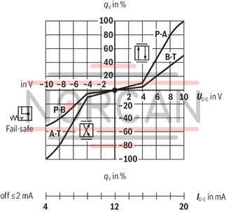
Pressure amplification


Frequency response


Symbols

|
With control symbol C1 and C5, the following applies: |
|
|
P → A: qvmax |
B → T: qv/2 |
|
P → B: qv/2 |
A → T: qvmax |

Installation side of the inductive position transducer

Version A1: Standard

Version F1: mA signal


|
1 |
Control system |
|
2 |
On the customer side |
|
3 |
Mating connector |
|
4 |
Valve |
|
5 |
Connection surface |
|
6 |
On the Rexroth side |
|
Version |
Multi-wire cable |
|
Litz wire structure, finely stranded according to VDE 0295, class 6 |
|
|
Protective earthing conductor, green-yellow |
|
|
Cu shielding braid |
|
|
Type |
e.g. oilflex-FD 855 CP (Lappkabel) |
|
Number of wires |
Is determined by valve type, connector type and signal assignment |
|
Line diameter |
0,75 mm2 ... 20 m length |
|
External diameter |
9,4 ... 11,8 mm - Pg11 12,7 ... 13,5 mm - Pg16 |
Notice:
Supply voltage 24 VDCnom, if 18 VDC are undershot, there will be an internal fast shut-down, comparable to “Enable OFF”.
Additionally with version “F1”:
ID – E ≥ 3 mA – Valve is active
ID – E ≤ 2 mA – Valve is deactivated.
Electrical signals provided via control electronics (e. g. actual value) must not be used to switch off safety-relevant machine functions. (See also the European standard "Safety requirements for fluid-powered systems and their components - Hydraulics", EN 982!)
Block diagram / pin assignment version A1

Pin assignment 6P+PE; version "A1"

Block diagram / pin assignment version F1

Pin assignment 6P+PE; version "F1"

Dimensions in mm

|
1 |
Valve housing |
|
2 |
Integrated electronics (OBE) |
|
3 |
Identical seal rings for ports A, B, P and T (T1) |
|
4 |
Mating connector, separate order |
|
5 |
Control solenoid with position transducer |
|
6 |
Machined valve contact surface; Porting pattern according to ISO 4401-05-04-0-05 |
|
Subplates must be ordered separately |
|
Valve mounting screws (separate order):
4 hexagon socket head cap screws ISO 4762 - M6 x 40 - 10.9-N67F82170
Tightening torque MA = 11 + 3 Nm , material no. 2910151209
or
4 hexagon socket head cap screws ISO 4762 - M6 x 40 - 10.9
For valves with round connector

For valves with round connector
Service case with test unit for proportional servo valves with integrated electronics (OBE)
VT-VETSY-1-1X
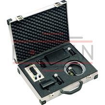
Service case with test unit for proportional servo valves with integrated electronics (OBE)
VT-VETSY-1-1X
Component series 1XData sheet
Configurator / CAD
Spare parts & repair