
BOSCH REXROTH
0811404901
$6,795.13 USD
- BOSCH REXROTH
- Material:0811404901
- Model:4WRPH10C1B100L-2X/G24K0/M-750
Quantity in stock: 0
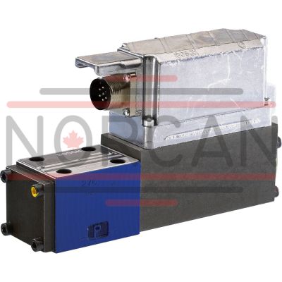
The Bosch Rexroth 4WRPH10C1B100L-2X/G24K0/M ('0811404901') is a direct operated high-response industrial hydraulic valve designed for precise and rapid control of oil flow direction. This size 10 valve features symbol C1, an external amplifier, and operates on a 24 V DC power supply. It is characterized by its linear flow characteristics and high accuracy, which is ensured by an external piston position feedback mechanism. Valves of the 4WRPH-750 series, to which this model belongs, are known for their servo quality performance and robust design that can withstand challenging environmental conditions. The design includes a control spool and sleeve that are actuated on one side, with the capability to revert to a 4/4 fail-safe position when deactivated. This feature makes it particularly suitable for safety-critical applications. The 'Ruggedized' design of this valve indicates that it can endure significant mechanical stress (up to 40 g) and has a central connector for ease of use. Its suitability for the wood industry and other installations facing aggravated environmental conditions demonstrates its reliability in harsh settings. For mounting purposes, the valve follows the porting pattern according to ISO 4401 standards for subplate mounting, ensuring compatibility with various hydraulic systems. The combination of its high-response capabilities and durable construction makes this Bosch hydraulic valve an essential component for sophisticated industrial applications requiring precise fluid control under demanding circumstances.
Size 10, symbol C1, external amplifier, 24 V DC
Industrial hydraulic valve in a high performance range. Reliable and quick control of the direction of the oil flow according to hydraulic symbol. High accuracy thanks to external piston position feedback.
Unpacked Weight: 6.89334 kg
Valves of type 4WRPH-750 are direct operated high-response valve in servo quality with electric position feedback and robust design. The valves are actuated on one side and in their deactivated condition take a 4/4 fail-safe position. They are suitable for use in the wood industry and in installations with aggravated environmental conditions
| Spool valve |
| Direct actuated |
| Linear flow characteristics |
| Linear flow characteristics |
| Data Sheet | Download Data Sheet |
| 3D CAD | Download 3D CAD |
| Manual | Download Manual |
| Manual | Download Manual |
| Manual | Download Manual |
| Manual | Download Manual |
| Manual | Download Manual |
| Spool symbol | Symbol C1 |
| Max. pressure | 315 |
| Electrical connection description | Connector 3-pole (2 + PE) according to EN 175301-803 |
| Productgroup ID | 9,10,11,12,13,14 |
| Number of ports | 4 |
| Type of actuation | Electrical with external electronics |
| Size | 10 |
| Electrical connector | Connector 3-pole (2 + PE) |
| Type of connection | Subplate mounting |
| Connection diagram NFPA | NFPA T3.5.1 R2-2002 D05 |
| Size_CETOP | D05 |
| Nominal flow | 100 |
| Connection diagram | ISO 4401-05-04-0-05 |
| Supply voltage | 24 VDC |
| Number of switching positions | 4 |
| Weight | 6.89334 |
| Seals | NBR |
| Hydraulic fluid | HL,HLP,HLPD,HVLP,HVLPD,HFC |
| Conformity | CE,RoHS |
|
01 |
02 |
03 |
04 |
05 |
06 |
07 |
08 |
09 |
10 |
11 |
12 |
13 |
||||
|
4 |
WRP |
H |
B |
‒ |
2X |
/ |
G24 |
K0 |
/ |
M |
‒ |
750 |
|
01 |
4 main ports |
4 |
|
02 |
High-response directional valve, direct operated |
WRP |
|
03 |
Control spool/sleeve |
H |
|
04 |
Size 6 |
6 |
|
Size 10 |
10 |
|
|
05 |
Symbols; for the possible version, see "Symbols/Circuit diagrams" |
C1, C3, C4, C5 |
|
Installation side of the inductive position transducer |
||
|
06 |
Valve side B (standard) (see "Symbols/Circuit diagrams") |
B |
|
Rated flow at 70 bar valve pressure differential (35 bar/control edge) |
||
|
07 |
12 l/min |
12 |
|
15 l/min |
15 1) |
|
|
24 l/min |
24 |
|
|
25 l/min |
25 1) |
|
|
40 l/min |
40 3) |
|
|
50 l/min |
50 |
|
|
100 l/min |
100 |
|
|
Flow characteristic |
||
|
08 |
Linear |
L |
|
Inflected characteristic curve |
P 2) |
|
|
09 |
Component series 20 ... 29 (20 ... 29: unchanged installation and connection dimensions) - Size 6 |
2X |
|
Supply voltage of the control electronics |
||
|
10 |
Direct voltage 24 V |
G24 |
|
Electrical connection |
||
|
11 |
Without mating connector; connector DIN 43563-AM6 |
K0 |
|
Seal material |
||
|
12 |
NBR seals |
M |
|
13 |
Ruggedized design |
750 |
| 1) | Use only in connection with flow characteristics "P" |
| 2) | Inflected characteristic curve (inflection 60 % for NG6 with rated flows "15" and "25", otherwise inflection 40 %) |
| 3) | qv 2:1 only with rated flow = 40 l/min |
For applications outside these parameters, please consult us!
general
|
Type |
4WRPH...-750 | ||
|
Size |
6 | 10 | |
|
Component series |
2X | ||
|
Type of actuation |
Proportional solenoid with position control, electrical amplifier external | ||
|
Type of connection |
For subplate mounting: Porting pattern according to ISO 4401 | ||
|
Installation position |
Any | ||
|
Weight |
kg |
2.5 | 7 |
|
Ambient temperature range |
°C |
-20 … +60 | |
hydraulic
|
Type |
4WRPH...-750 | |||
|
Size |
6 | 10 | ||
|
Maximum operating pressure |
bar |
315 | ||
|
Maximum operating pressure |
Port P |
bar |
315 | |
|
Port A |
bar |
315 | ||
|
Port B |
bar |
315 | ||
|
Port T |
bar |
250 | ||
|
Maximum flow |
l/min |
40 | 100 | |
|
Nominal flow |
l/min |
12 15 24 40 |
50 100 |
|
|
Hydraulic fluid temperature range |
°C |
-20 … +70 | ||
|
Viscosity range |
Maximum admissible |
mm²/s |
10 … 800 | |
|
Recommended |
mm²/s |
20 … 100 | ||
|
Maximum admissible degree of contamination of the hydraulic fluid, cleanliness class according to ISO 4406 (c) 1) |
Class 18/16/13 according to ISO 4406 (c) | |||
|
Hysteresis |
% |
≤ 0.2 | ||
|
Manufacturing tolerance |
% |
< 10 | ||
| 1) | The cleanliness classes specified for the components must be adhered to in hydraulic systems. Effective filtration prevents faults and simultaneously increases the life cycle of the components. For the selection of the filters, see www.boschrexroth.com/filter. |
hydraulic
|
Nominal flow |
l/min |
12 1) | 15 1) | 24 1) | 40 1) | 50 2) | 50 3) | 100 2) | 100 3) | |
|
Limitation of use |
Symbols C, C3, C5 |
bar |
315 | 160 | 315 | 160 | ||||
|
Symbols C1, C4 |
bar |
315 | 280 | 250 | 100 | 250 | 100 | |||
|
Leakage flow (at 100 bar) |
Linear characteristic curve “L” |
l/min |
< 300 | - | < 500 | < 900 | < 1200 | < 1500 | < 1000 | |
|
Inflected characteristic curve "P" |
l/min |
- | < 180 | < 300 | < 450 | < 600 | < 500 | < 600 | ||
| 1) | With Δp = 35 bar/control edge |
| 2) | At Δp = 35 bar/control edge, area ratio 1:1 |
| 3) | At Δp = 35 bar/control edge, area ratio 2:1 |
electrical
|
Type |
4WRPH...-750 | |||
|
Size |
6 | 10 | ||
|
Power supply |
Nominal voltage |
V |
24 | |
|
Maximum solenoid current |
A |
2.7 | 3.7 | |
|
Coil resistance with solenoid temperature 20 °C |
Ω |
2.5 | 2.4 | |
|
Duty cycle |
% |
100 | ||
|
Maximum power consumption |
VA |
40 | ||