


BOSCH REXROTH
0811405064
- BOSCH REXROTH
- Material:0811405064
- Model:VT-VRRA 1-527-20/V0/PO-IS
Due to extremely high demand, please call 877-366-7226 for availability
The Bosch Rexroth VT-VRRA 1-527-20/V0/PO-IS (0811405064) is a sophisticated hydraulic control device designed to deliver precise closed-loop position control with PID characteristics, ensuring high levels of accuracy in applications requiring dynamic response. Its controlled output stage is engineered for rapid energization and deletion, facilitating exceptionally short actuating times that are essential in fast-paced operational environments. The unit is equipped with an enable input feature, which provides an additional layer of operational safety by allowing the device to be activated only when it is safe and necessary to do so. Moreover, the outputs of this model are short-circuit-proof, enhancing the reliability and longevity of the device by protecting it against potential electrical mishaps. A notable capability of the Bosch VT-VRRA 1-527-20/V0/PO-IS is its adjustable zero point function. This feature allows for fine-tuning to achieve precise control alignment with system requirements, thereby optimizing performance. Additionally, this model includes cable break detection for the actual value cable, which serves as a diagnostic tool to promptly identify any discontinuities in connectivity that could compromise system accuracy or cause downtime. Overall, this product represents a high-quality solution for applications demanding exacting hydraulic control with robust safety and diagnostic features. Its fast response times and precision control make it suitable for use in advanced automation systems where reliability and accuracy are paramount.
|
01 |
Valve amplifier for high-response valves with one solenoid, analog, euro-card format |
VT-VRRA1 |
|
02 |
For valves: 3WRCB 25…50…M-1X… |
527 |
|
03 |
Component series 20 ... 29 (20 ... 29: unchanged technical data and pin assignment) |
2X |
|
04 |
Version: standard |
V0 |
|
05 |
For block installation valve with control A → X |
PO-IS |
|
01 |
02 |
03 |
04 |
05 |
||||
|
VT-VRRA1 |
‒ |
527 |
‒ |
2X |
/ |
V0 |
/ |
PO-IS |
General
|
Component series |
2X | |
|
Type of electronics |
Analog | |
|
Design |
Euro-card |
Voltage supply
|
Operating voltage |
nominal |
U |
V |
24 |
|
Lower limit value |
UB(t)min |
V |
21 | |
|
Upper limit value |
UB(t)max |
V |
40 | |
|
Ripple 1) |
% |
< 10 | ||
|
Power consumption |
P |
VA |
37 | |
|
Current consumption |
max. |
Imax |
A |
1.7 |
| 1) | In case of ripple > 10 %, an upstream smoothing capacitor is required (recommendation: capacitor module VT 11110) |
Analog inputs
|
Command value source |
Potentiometer 10 kΩ supplied with 10 V internal reference voltage, external signal source | ||||
|
Command value |
Voltage |
Differential input |
U |
V |
0 ... ±10 |
|
Input resistance |
R |
kΩ |
≥ 100 | ||
Digital inputs
|
Enable 1) |
On (active) |
U |
V |
8.5 ... 40 |
| 1) | RE = 100 kΩ |
Digital outputs
|
Cable break error message |
No error 1) |
UB |
V |
24 |
|
Error |
UB |
V |
0 |
| 1) | Imax = 100 mA |
Solenoid outputs
|
Solenoid current |
max. |
Imax |
A |
2.7 |
|
Solenoid output |
other properties |
Clocked current controller | ||
|
Cable length |
for 1.5 mm2 |
L |
m |
20 |
|
for 2.5 mm2 |
L |
m |
60 |
Position transducer
|
Line cross-section |
Position transducer line |
A |
4 x 0.5 mm2 (shielded) | |
|
Position transducer supply |
U |
V |
±15 | |
Adjustment options
|
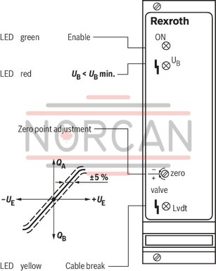
Zero point calibration setting range |
% |
± 5 |
Displays
|
LED display |
Green 1 |
Enable | |
|
Yellow 1 |
Cable break actual value | ||
|
Red |
UB too low |
Other information
|
Reference voltage |
Potentiometer supply |
U |
V |
±10 (Imax = 10 mA) |
|
Special features |
Short-circuit-proof outputs, cable break detection for actual value line, position control with PID behavior, fast energization and fast deletion for short actuating times | |||
|
Anschlussart |
32-pin male connector, DIN 41612, form F | |||
|
Ambient temperature range |
ϑ |
°C |
0 … 70 | |
|
Storage temperature range |
ϑ |
°C |
-20 … 70 | |
|
Weight |
m |
kg |
0.36 | |
For applications outside these parameters, please consult us!
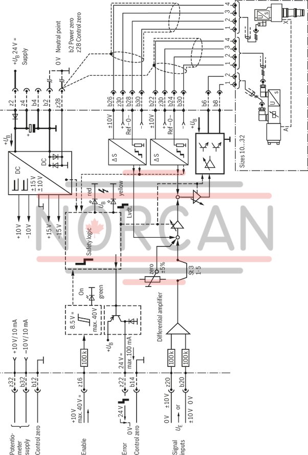
Dimensions in mm
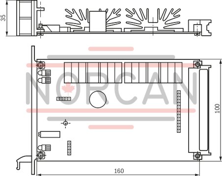
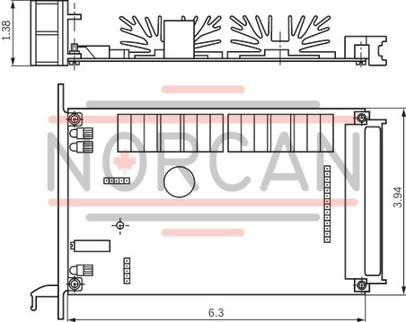
Dimensions in mm
The amplifier card may only be unplugged and plugged when de-energized.
The distance to aerial lines, radios, and radar systems has to be at least 1 m.
Do not lay solenoid and signal lines near power cables.
For signal lines and solenoid conductors, we recommend using shielded cables.
The cable shield must be connected to the control cabinet extensively and as short as possible.
The valve solenoid must not be connected to free-wheeling diodes or other protection circuits.
The cable lengths and cross-sections specified in the technical data must be complied with.
Wiring information
Power zero b2 and control zero b12 or b14 or z28 must be separately led to the central ground (neutral point).