

BOSCH REXROTH
0811405095
$1,790.76 USD
- BOSCH REXROTH
- Material:0811405095
- Model:VT-VRPA1-527-10/V0
Quantity in stock: 0
The Bosch Rexroth VT-VRPA 1-527-1X/V0 (0811405095) is a sophisticated component designed for precise closed-loop position control with PID characteristics, ensuring accurate and responsive control for various applications. This model features a controlled output stage that provides fast energization and deletion, enabling short actuating times that are critical in dynamic systems requiring quick responses. The inclusion of an enable input adds an extra layer of operational safety, allowing the device to be activated or deactivated as needed within a circuit. Moreover, the VT-VRPA 1-527-1X/V0 is designed with robustness in mind, featuring short-circuit-proof outputs to ensure longevity and reliability even in demanding conditions. The adjustability of the zero point and sensitivity allows for fine-tuning to match specific application requirements, enhancing the versatility and adaptability of this component across different use cases. Its high-performance capabilities make it suitable for integration into complex machinery where precise positioning is paramount. With its advanced features and Bosch's reputation for quality engineering, the VT-VRPA 1-527-1X/V0 (0811405095) stands out as a key component for systems where precision control is not just desired but essential. Whether utilized in industrial automation or other sectors requiring exact motion regulation, this product delivers on performance and durability.
|
01 |
Valve amplifier for high-response valves with one solenoid, analog, euro-card format |
VT-VRPA1 |
|
02 |
For valves: DBETFX, DREB6X, 4WRP6EA, 3FREZ |
527 |
|
03 |
Component series 10 ... 19 (10 ... 19: unchanged installation and connection dimensions) |
1X |
|
04 |
Version: standard |
V0 |
|
05 |
Option: Pressure valves |
PV |
|
Option: Throttle/flow control valves |
QV |
|
|
01 |
02 |
03 |
04 |
05 |
||||
|
VT-VRPA1 |
‒ |
527 |
‒ |
1X |
/ |
V0 |
/ |
Position transducer
|
Cable length |
L |
50 m at 100 pF/m |
Supplementary information
|
Reference voltage |
Potentiometer supply |
U |
V |
10 (Imax = 50 mA) |
|
Special features |
Short-circuit-proof outputs, cable break detection for actual value line, position control with PID behavior, fast energization and fast deletion for short actuating times | |||
|
Anschlussart |
32-pin male connector, DIN 41612, form F | |||
|
Ambient temperature range |
ϑ |
°C |
0 … 70 | |
|
Storage temperature range |
ϑ |
°C |
-20 … 70 | |
|
Weight |
m |
kg |
0.37 | |
Anzeigen
|
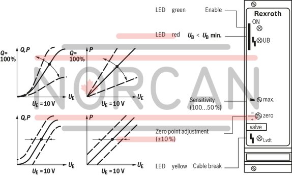
LED display |
Green 1 |
Enable | |
|
Yellow 1 |
Cable break actual value | ||
|
Red |
UB too low |
Adjustment options
|
Zero point calibration |
% |
± 10 | ||
|
Range sensitivity adjustment |
Setting condition |
% |
50 ... 100 | |
Solenoid outputs
|
Solenoid current |
max. |
Imax |
A |
2.7 |
|
Power |
P |
VA |
25 | |
|
Solenoid output |
other properties |
clocked | ||
|
Cable length |
for 1.5 mm2 |
m |
20 | |
|
for 2.5 mm2 |
m |
60 | ||
Analog outputs
|
Test point 1) |
Actual value |
0 ... 10 |
| 1) | 0 V at solenoid current = 0 ( output stage not enabled), 10 V at solenoid current = maximum |
Analog inputs
|
Command value source |
Potentiometer 1 kΩ supplied with 10 V internal reference voltage, external signal source | ||||
|
Command value |
Voltage (differential input) |
U |
V |
0 ... 10 | |
|
Voltage |
grounded on one side, first input |
Ucommand |
V |
0 … 10 | |
|
Voltage |
grounded on one side, second input |
Ucommand |
V |
0 … 10 | |
|
Actual value valve |
Voltage |
U |
10.2 (7.8 kHz) | ||
Voltage supply
|
Operating voltage |
nominal |
U |
V |
24 |
|
Lower limit value |
UB(t)min |
V |
21 | |
|
Upper limit value |
UB(t)max |
V |
40 | |
|
Ripple 1) |
% |
< 10 | ||
|
Power consumption |
max. |
Smax |
VA |
35 |
|
Current consumption |
max. |
Imax |
A |
1.5 |
| 1) | In case of ripple > 10 %, an upstream smoothing capacitor is required (recommendation: capacitor module VT 11110) |
Digital outputs
|
Cable break error message |
No error 1) |
U |
V |
24 V |
|
Error |
U |
V |
0 V |
| 1) | Imax = 100 mA |
Digital inputs
|
Enable |
On (active) |
U |
V |
8.5 ... 40 |
General
|
Component series |
1X | ||
|
Material number |
Data sheet |
1819929062 | |
|
Type of electronics |
Analog | ||
|
Design |
Euro-card | ||
For applications outside these parameters, please consult us!
2/2 directional seat valve (“NK”) and 3/2 directional seat valve (“CK”)
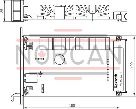
Dimensions in mm
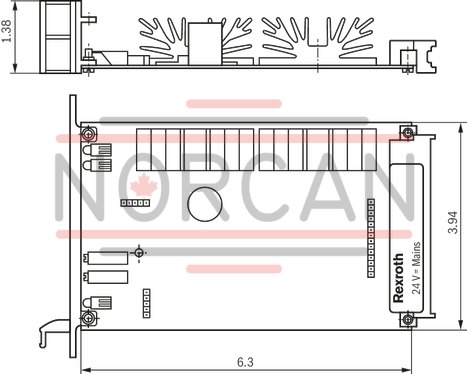
Dimensions in mm
The amplifier card may only be unplugged and plugged when de-energized.
The distance to aerial lines, radios, and radar systems has to be at least 1 m.
Do not lay solenoid and signal lines near power cables.
For signal lines and solenoid conductors, we recommend using shielded cables.
The cable shield must be connected to the control cabinet extensively and as short as possible.
The valve solenoid must not be connected to free-wheeling diodes or other protection circuits.
The cable lengths and cross-sections specified in the technical data must be complied with.
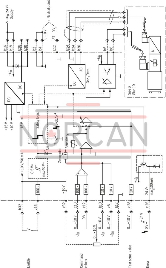
Wiring information
Power zero b2 and control zero b12 are to be bridged.
If the power supply unit is < 1 m away, directly to DIN connector.
In case of distances > 1 m, lead the control zero separately to the ground.