

BOSCH REXROTH
0811405099
$1,597.90 USD
- BOSCH REXROTH
- Material:0811405099
- Model:VT-VRPA1-537-10V0/QV
Quantity in stock: 0
The Bosch Rexroth VT-VRPA1-537-1X/V0/QV (0811405099) is a sophisticated proportional valve amplifier designed for precise control in hydraulic systems. This model features a controlled output stage that allows for closed-loop position control with PID characteristics, ensuring high accuracy and stability in the operation of connected hydraulic actuators. The amplifier is characterized by its rapid energization and deletion capabilities, which contribute to notably short actuating times, enhancing the responsiveness of the system it is integrated into. Additionally, the VT-VRPA1-537-1X/V0/QV comes equipped with an enable input function that provides an added layer of operational safety, allowing the system to be activated only when necessary. Its outputs are short-circuit-proof, offering protection against potential electrical faults and ensuring continued reliability of the system. Users will appreciate the adjustable zero point and sensitivity features that allow for fine-tuning to meet specific application requirements. A noteworthy feature of this model is its cable break detection mechanism for the actual value cable, which enhances diagnostic capabilities by promptly identifying issues related to signal transmission disruptions. This ensures maintenance can be carried out swiftly to minimize downtime. Overall, Bosch's VT-VRPA1-537-1X/V0/QV proportional valve amplifier represents a high-performance component suitable for dynamic hydraulic applications where precision and speed are critical. It stands out for its robust design aimed at delivering consistent performance and protecting against electrical anomalies while providing user-friendly adjustability options.
|
01 |
Valve amplifier for high-response valves with one solenoid, analog, euro-card format |
VT-VRPA1 |
|
02 |
For valves: DBEB10Z, DREB10Z, DBETBX, 4WRP10EA |
537 |
|
03 |
Component series 10 ... 19 (10 ... 19: unchanged installation and connection dimensions) |
1X |
|
04 |
Version: standard |
V0 |
|
05 |
Option: Pressure valves |
PV |
|
Option: Throttle/flow control valves |
QV |
|
|
01 |
02 |
03 |
04 |
05 |
||||
|
VT-VRPA1 |
‒ |
537 |
‒ |
1X |
/ |
V0 |
/ |
Position transducer
|
Cable length |
L |
50 m at 100 pF/m |
Supplementary information
|
Reference voltage |
Potentiometer supply |
U |
V |
10 (Imax = 50 mA) |
|
Special features |
Short-circuit-proof outputs, cable break detection for actual value line, position control with PID behavior, fast energization and fast deletion for short actuating times | |||
|
Anschlussart |
32-pin male connector, DIN 41612, form F | |||
|
Ambient temperature range |
ϑ |
°C |
0 … 70 | |
|
Storage temperature range |
ϑ |
°C |
-20 … 70 | |
|
Weight |
m |
kg |
0.37 | |
Anzeigen
|
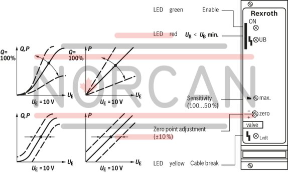
LED display |
Green 1 |
Enable | |
|
Yellow 1 |
Cable break actual value | ||
|
Red |
UB too low |
Adjustment options
|
Zero point calibration |
% |
± 10 | ||
|
Range sensitivity adjustment |
Setting condition |
% |
50 ... 100 | |
Solenoid outputs
|
Solenoid current |
max. |
Imax |
A |
3.7 |
|
Power |
P |
VA |
50 | |
|
Solenoid output |
other properties |
clocked | ||
|
Cable length |
for 1.5 mm2 |
m |
20 | |
|
for 2.5 mm2 |
m |
60 | ||
Analog outputs
|
Test point 1) |
Actual value |
0 ... 10 |
| 1) | 0 V at solenoid current = 0 ( output stage not enabled), 10 V at solenoid current = maximum |
Analog inputs
|
Command value source |
Potentiometer 1 kΩ supplied with 10 V internal reference voltage, external signal source | ||||
|
Command value |
Voltage (differential input) |
U |
V |
0 ... 10 | |
|
Voltage |
grounded on one side, first input |
Ucommand |
V |
0 … 10 | |
|
Voltage |
grounded on one side, second input |
Ucommand |
V |
0 … 10 | |
|
Actual value valve |
Voltage |
U |
10.2 (7.8 kHz) | ||
Voltage supply
|
Operating voltage |
nominal |
U |
V |
24 |
|
Lower limit value |
UB(t)min |
V |
21 | |
|
Upper limit value |
UB(t)max |
V |
40 | |
|
Ripple 1) |
% |
< 10 | ||
|
Power consumption |
max. |
Smax |
VA |
60 |
|
Current consumption |
max. |
Imax |
A |
2.5 |
| 1) | In case of ripple > 10 %, an upstream smoothing capacitor is required (recommendation: capacitor module VT 11110) |
Digital outputs
|
Cable break error message |
No error 1) |
U |
V |
24 V |
|
Error |
U |
V |
0 V |
| 1) | Imax = 100 mA |
Digital inputs
|
Enable |
On (active) |
U |
V |
8.5 ... 40 |
General
|
Component series |
1X | ||
|
Material number |
Data sheet |
1819929062 | |
|
Type of electronics |
Analog | ||
|
Design |
Euro-card | ||
For applications outside these parameters, please consult us!
2/2 directional seat valve (“NK”) and 3/2 directional seat valve (“CK”)
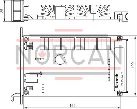
Dimensions in mm
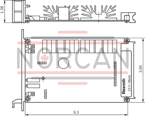
Dimensions in mm
The amplifier card may only be unplugged and plugged when de-energized.
The distance to aerial lines, radios, and radar systems has to be at least 1 m.
Do not lay solenoid and signal lines near power cables.
For signal lines and solenoid conductors, we recommend using shielded cables.
The cable shield must be connected to the control cabinet extensively and as short as possible.
The valve solenoid must not be connected to free-wheeling diodes or other protection circuits.
The cable lengths and cross-sections specified in the technical data must be complied with.
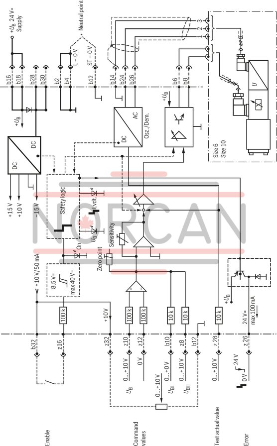
Wiring information
Power zero b2 and control zero b12 are to be bridged.
If the power supply unit is < 1 m away, directly to DIN connector.
In case of distances > 1 m, lead the control zero separately to the ground.