

BOSCH REXROTH
0811405104
$1,760.59 USD
- BOSCH REXROTH
- Material:0811405104
- Model:VT-VRPA1-537-10/V0/QV-RTP
Quantity in stock: 0
The Bosch Rexroth VT-VRPA 1-537-1X/V0/QV-RTP (0811405104) is a sophisticated pneumatic control valve designed for precise closed-loop position control, integrating PID characteristics to ensure optimal performance in various applications. This model boasts a controlled output stage that provides quick energization and deletion, facilitating short actuating times essential for high-speed operations. The enable input feature enhances operational safety, allowing the user to initiate control when necessary. Equipped with short-circuit-proof outputs, the Bosch VT-VRPA 1-537-1X/V0/QV-RTP valve ensures reliability and durability even in demanding environments where electrical anomalies may occur. Users can fine-tune the system's performance through adjustable zero point and sensitivity settings, enabling customization for specific application requirements. This level of adjustability makes it ideal for integration into systems where precision and adaptability are paramount. The valve's robust construction and advanced control features make it suitable for use in a variety of sectors that require meticulous flow or pressure management. Its fast response times are particularly beneficial in applications where rapid changes in control parameters are needed, such as in automated manufacturing processes or robotics. Overall, the Bosch VT-VRPA 1-537-1X/V0/QV-RTP (0811405104) represents a reliable solution for users seeking a high-performance pneumatic control valve capable of delivering precise positional adjustments with fast response times and adaptable settings to meet the exacting demands of sophisticated industrial applications.
|
01 |
Valve amplifier for high-response valves with one solenoid, analog, euro-card format |
VT-VRPA1 |
|
02 |
For valves: DBEB10Z, DREB10Z, DBETBX, 4WRP10EA |
537 |
|
03 |
Component series 10 ... 19 (10 ... 19: unchanged installation and connection dimensions) |
1X |
|
04 |
Version: standard |
V0 |
|
05 |
Option: Pressure valves |
PV |
|
Option: Throttle/flow control valves |
QV |
|
|
06 |
Adjustable ramp that can be switched off |
RTP |
|
01 |
02 |
03 |
04 |
05 |
06 |
|||||
|
VT-VRPA1 |
‒ |
537 |
‒ |
1X |
/ |
V0 |
/ |
‒ |
RTP |
Position transducer
|
Cable length |
L |
50 m at 100 pF/m |
Supplementary information
|
Reference voltage |
Potentiometer supply |
U |
V |
10 (Imax = 50 mA) |
|
Special features |
Short-circuit-proof outputs, cable break detection for actual value line, position control with PID behavior, fast energization and fast deletion for short actuating times | |||
|
Anschlussart |
32-pin male connector, DIN 41612, form F | |||
|
Ambient temperature range |
ϑ |
°C |
0 … 70 | |
|
Storage temperature range |
ϑ |
°C |
-20 … 70 | |
|
Weight |
m |
kg |
0.36 | |
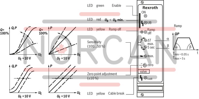
Anzeigen
|
LED display |
Green 1 |
Enable | |
|
Yellow 1 |
Cable break actual value | ||
|
Yellow 2 |
Ramp off | ||
|
Red |
UB too low |
Adjustment options
|
Zero point calibration |
% |
± 10 | ||
|
Range sensitivity adjustment |
Setting condition |
% |
50 ... 100 | |
|
Ramp time up/down |
Ramp 1 |
t |
s |
0.05 … 5 |
Solenoid outputs
|
Solenoid current |
max. |
Imax |
A |
3.7 |
|
Power |
P |
VA |
50 | |
|
Solenoid output |
other properties |
clocked | ||
|
Cable length |
for 1.5 mm2 |
m |
20 | |
|
for 2.5 mm2 |
m |
50 | ||
Analog outputs
|
Test point 1) |
Actual value |
0 ... 10 |
| 1) | 0 V at solenoid current = 0 ( output stage not enabled), 10 V at solenoid current = maximum |
Analog inputs
|
Command value source |
Potentiometer 1 kΩ supplied with 10 V internal reference voltage, external signal source | ||||
|
Command value |
Voltage (differential input) |
U |
V |
0 ... 10 | |
|
Voltage |
grounded on one side, first input |
Ucommand |
V |
0 … 10 | |
|
Voltage |
grounded on one side, second input |
Ucommand |
V |
0 … 10 | |
|
Actual value valve |
Voltage |
U |
10.2 (7.8 kHz) | ||
Voltage supply
|
Operating voltage |
nominal |
U |
V |
24 |
|
Lower limit value |
UB(t)min |
V |
21 | |
|
Upper limit value |
UB(t)max |
V |
40 | |
|
Ripple 1) |
% |
< 10 | ||
|
Power consumption |
max. |
Smax |
VA |
60 |
|
Current consumption |
max. |
Imax |
A |
2.5 |
| 1) | In case of ripple > 10 %, an upstream smoothing capacitor is required (recommendation: capacitor module VT 11110) |
Digital outputs
|
Cable break error message |
No error 1) |
U |
V |
24 V |
|
Error |
U |
V |
0 V |
| 1) | Imax = 100 mA |
Digital inputs
|
Enable |
On (active) |
U |
V |
8.5 ... 40 |
|
External ramp switch-off |
Without ramp |
U |
V |
8.5 ... 40 |
|
With ramp |
U |
V |
8.5 ... 40 |
General
|
Component series |
1X | ||
|
Material number |
Data sheet |
1819929063 | |
|
Type of electronics |
Analog | ||
|
Design |
Euro-card | ||
For applications outside these parameters, please consult us!
2/2 directional seat valve (“PK”) and 3/2 directional seat valve (“UK”)
Dimensions in mm
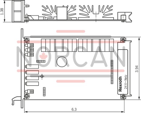
Dimensions in mm

The amplifier card may only be unplugged and plugged when de-energized.
The distance to aerial lines, radios, and radar systems has to be at least 1 m.
Do not lay solenoid and signal lines near power cables.
For signal lines and solenoid conductors, we recommend using shielded cables.
The cable shield must be connected to the control cabinet extensively and as short as possible.
The valve solenoid must not be connected to free-wheeling diodes or other protection circuits.
The cable lengths and cross-sections specified in the technical data must be complied with.
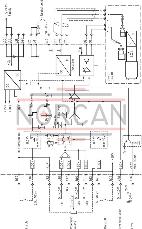
Wiring information
Power zero b2 and control zero b12 are to be bridged.
If the power supply unit is < 1 m away, directly to DIN connector.
In case of distances > 1 m, lead the control zero separately to the ground.
Information on ramp use
Ramp ON: No signal at b20.
Ramp OFF: 8.5...40 V at b20 or connection between b22 and b20.
In case of ramp OFF or cable break, any ramp started before will be canceled. Transition to the signal end value is realized in one step.