

BOSCH REXROTH
0811405126
- BOSCH REXROTH
- Material:0811405126
- Model:VT-MSPA1-508-10/V0
Due to extremely high demand, please call 877-366-7226 for availability
The Bosch Rexroth VT-MSPA 1-508-10/V0 (0811405126) is a sophisticated control device designed for precision regulation in hydraulic applications. This model is equipped with a differential input for voltage, which allows for fine-tuned control over the connected systems. It features a ramp generator with separately adjustable ramp times for both "up" and "down" operations, enabling smooth transitions and reducing the risk of system shocks during start-up or shut-down processes. An adjustable zero point and sensitivity function provide additional layers of customization, ensuring that the device can be finely calibrated to meet specific operational requirements. The clocked power output stage ensures that energy is delivered in precise intervals, enhancing efficiency and control. For ease of monitoring, the VT-MSPA 1-508-10/V0 is fitted with LED displays that indicate various operating states at a glance. This immediate feedback allows for quick diagnostics and adjustments as needed to maintain optimal performance. Additionally, it features a removable connector strip which simplifies installation and maintenance by allowing easy disconnection without having to rewire the entire system. Overall, this model represents a high level of engineering excellence, offering robust performance and versatile control options suitable for a range of hydraulic systems where precision and reliability are paramount.
|
01 |
Valve amplifier for proportional valves without electrical position feedback, Analog, Modular design |
VT-MSPA1 |
|
02 |
For valves: |
508 |
|
03 |
Component series 10 ... 19 (10 ... 19: unchanged installation and connection dimensions) |
1X |
|
04 |
Version: standard |
V0 |
|
01 |
02 |
03 |
04 |
|||
|
VT-MSPA1 |
‒ |
508 |
‒ |
1X |
/ |
V0 |
General
|
Component series |
1X | ||
|
Material number |
Data sheet |
1819929085 | |
|
Type of electronics |
Analog | ||
|
Design |
Modul | ||
Voltage supply
|
Operating voltage |
nominal |
U |
V |
24 |
|
Lower limit value |
UB(t)min |
V |
21 | |
|
Upper limit value |
UB(t)max |
V |
40 | |
|
Power consumption |
max. |
Smax |
VA |
30 |
|
Current consumption |
max. |
Imax |
A |
1.25 |
Analog inputs
|
Command value source |
Potentiometer 10 kΩ supplied with 10 V internal reference voltage, external signal source | ||||
|
Command value |
Voltage (differential input) |
U |
V |
0 ... 10 | |
|
Voltage (differential input) |
Input resistance |
R |
kΩ |
≥ 100 | |
Digital inputs
|
Ramp switch-off |
U |
V |
6 ... 40 |
Solenoid outputs
|
Solenoid current |
max. |
Imax |
A |
0.8 |
|
Solenoid output |
Power |
Smax |
VA |
25 |
|
Solenoid output |
other properties |
Clocked current controller | ||
|
Cable length |
for 1.5 mm2 |
L |
m |
20 |
|
for 2.5 mm2 |
L |
m |
50 |
Adjustment options
|
Zero point calibration information |
Set with Ue = 0.3 ... 0.5 V | |||
|
Sensitivity “gain” |
Setting condition |
With command value U = 10 V | ||
|
Zero point “zero” |
Setting condition |
With command value U = 0.3 ... 0.5 V | ||
|
Ramp time up/down |
t |
s |
0.05 … 5 | |
Displays
|
LED display |
Green |
Enable | |
|
yellow |
Ramp off | ||
|
red |
UB too low |
Supplementary information
|
Reference voltage |
Potentiometer supply |
U |
V |
10 (Imax = 10 mA) |
|
Special features |
Fast energization for short actuating time | |||
|
Anschlussart |
Connector, 10-pole (screw terminal) | |||
|
Mounting type |
Top hat rail TH35-7.5 or G rail G32 according to EN 60715 | |||
|
Ambient temperature range |
ϑ |
°C |
0 … 70 | |
|
Storage temperature range |
ϑ |
°C |
-20 … 70 | |
|
Weight |
m |
kg |
0.31 | |
For applications outside these parameters, please consult us!

Dimensions in mm

Dimensions in mm

The distance to aerial lines, radios and radar systems must be sufficient (> 1 m).
Do not lay solenoid and signal lines near power cables.
For signal lines and solenoid conductors, we recommend using shielded cables.
The cable shield must be connected to the control cabinet extensively and as short as possible.
The cable lengths and cross-sections specified must be complied with.
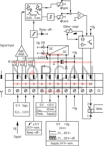
Use of ramps
Setting of ramp UP (accelerations) and ramp DOWN (braking) via 1 trimming potentiometer each.
ramp ON, if at the input connection 3 = 0 V (open) is applied.
Ramp OFF, if at the input connection 3 = 24 V is applied (switching range see technical data). In case of ramp OFF, any ramp started before will be canceled. Transition to the signal end value is effected by means of a step.
Settings
Setting zero: with 0.5 V signal (min. 0.3 V) at connection 2.
Setting max.: with 10 V signal at connection 2.