BOSCH REXROTH
0811405140
$3,059.14 USD
- BOSCH REXROTH
- Material:0811405140
- Model:VT-MACAS-500-10/V0/I
Quantity in stock: 0
The Bosch Rexroth VT-MACAS-500-10/V0/I (0811405140) is a sophisticated control module designed for precise manipulation of valves with integrated electronics that manage position and velocity. Engineered as a snap-on unit for carrier rails, this model showcases a streamlined installation process, ensuring secure and stable attachment within a variety of system configurations. The module is equipped with an enable input feature and incorporates cable break detection to monitor the integrity of the actual value cable, enhancing system reliability. Further contributing to its operational safety, the VT-MACAS-500-10/V0/I offers short-circuit-proof interfaces, reducing risks associated with electrical failures. Test points located on the front plate provide convenient access for system diagnostics and maintenance checks, facilitating routine monitoring without disrupting the overall setup. An optional feature within this module allows users to switch off the compensation jump, giving them control over specific performance aspects according to their application needs. In terms of control capabilities, the Bosch module delivers PT1 control for position adjustments and can execute PI control for velocity when used in conjunction with a tachometer or speed indicator. This dual functionality makes it versatile for applications requiring meticulous adjustments in both position and speed parameters. Additionally, its design supports area adjustment for cylinder operations, indicating that it can adapt to various actuator sizes or operational ranges within a system. The VT-MACAS-500-10/V0/I is thus characterized by its adaptability and precision control features, making it suitable for applications where accurate valve positioning and velocity adjustments are critical to system performance.


|
01 |
02 |
03 |
04 |
05 |
06 |
07 |
08 |
09 |
10 |
||||
|
VT- |
M |
A |
C |
A |
S |
– |
500 |
– |
1X |
/ |
V0 |
/ |
|
01 |
VT- |
|
|
02 |
M |
|
|
Hydraulic component |
||
|
03 |
Axis control |
A |
|
Type |
||
|
04 |
Controller |
C |
|
Control |
||
|
05 |
Analog |
A |
|
Function |
||
|
06 |
Position control |
S |
|
Serial number for types |
||
|
07 |
Standard variant without valve amplifier function |
500 |
|
08 |
Component series 10 ... 19 (10 ... 19: unchanged technical data and pin assignment) |
1X |
|
Customer version |
||
|
09 |
Catalog version |
V0 |
|
Option |
||
|
10 |
Marking variant with voltage input |
I |
|
Variant with current input |
Without |
|
General
|
Power supply |
nominal 24 V= battery voltage 21...40 V, rectified alternating voltage Ueff = 21...28 V (single-phase, full-wave rectifier) |
|||
|
Current consumption, max. |
mA |
200 | ||
|
Signal input |
VT-MACAS-500-10/V0 |
Ucommand: ±10 V, differential amplifier Ri= 100 kΩ |
||
|
VT-MACAS-500-10/V0/l |
Iist: 4...20 mA Rsh = 200 Ω |
|||
|
Actual value signal |
VT-MACAS-500-10/V0 |
Uactual: ±10 V, differential amplifier Ri= 100 kΩ |
||
|
VT-MACAS-500-10/V0/l |
Iist: 4...20 mA Rsh = 200 Ω |
|||
|
Valve signal |
UV= ±10 V (max. 10 mA) or IV= 4...20 mA (middle 12 mA) |
|||
|
Compensation step |
can be switched off; effective in a range of ±4 % |
|||
|
Enable signal |
V= |
8,5...40 V | ||
|
Error message |
no error: 24 Vnom (UB) max. 50 mA error: < 2 V |
|||
|
IN POS message |
IN POS: 24 Vnom (UB) max. 50 mA not IN POS: < 2 V |
|||
|
Ramp ranges |
I: 0,1...1 s II: 1...10 s |
|||
|
Area adjustment AK : AR |
min. 1:1; max. 1:4 | |||
|
Actual value adjustment |
Zero point: -5...10 % Gain: 50...110 % |
|||
|
Controller type |
Position: PT1 Velocity: PI |
|||
|
Zero point valve |
% |
± 5 | ||
|
Special features |
– Switchable from position to velocity control – Switchable position window – Test points on front plate – Interfaces short-circuit-proof |
|||
|
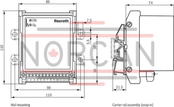
Fastening |
Top hat rail TH35-7.5 or G rail G32 according to EN 60715 | |||
|
Connection |
Connectors + terminals | |||
|
Operating temperature |
°C |
0 … +70 | ||
|
Storage temperature range |
°C |
-20 … +70 | ||
|
Weight |
m |
kg |
0.38 | |
For applications outside these parameters, please consult us!
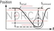
Ideal development (without command value ramps)
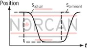
"Overshooting“, p gain too high, → Rotate switch KP against 1
"Creeping into the position“, p gain too low, → Rotate switch KP against 16
"Vibrations“, time constant too small, → Rotate switch KT1 against 16

"Area ratio wrong"; set symmetric motion sequence by means of switch A/B
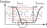
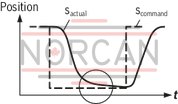
Ideal development (without command value ramps)
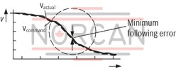
P gain too small, → Rotate switch KP against 16
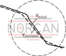
P gain too large, → Rotate switch KP against 1

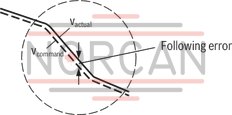
P gain correct, however following error too large, minimization of the following error by means of the I controller → Rotate switch KI until the min. following error is reached
Front plate

Block diagram with pin assignment

Wiring diagram AVPC-V
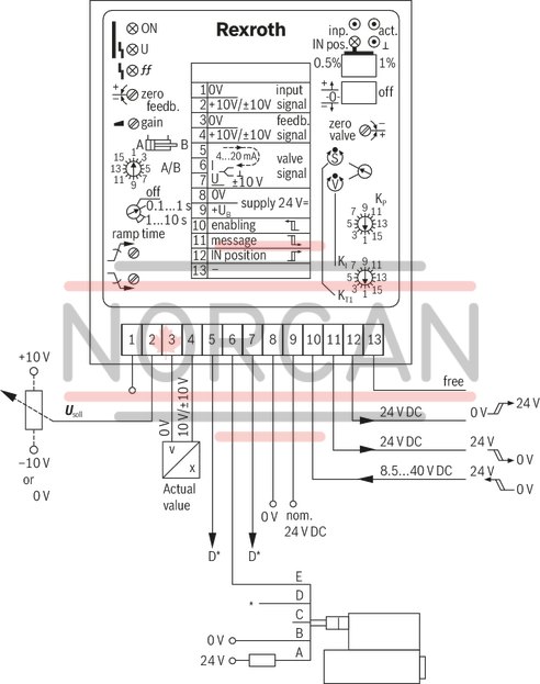
D* valve signal for valve with voltage or current interface
Wiring diagram AVPC-mA
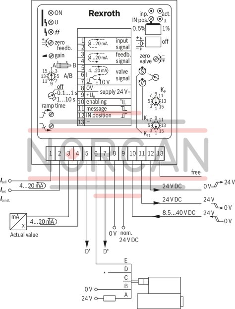
D* valve signal for valve with voltage or current interface
Dimensions in mm