


BOSCH REXROTH
0811405157
- BOSCH REXROTH
- Material:0811405157
- Model:VT-VACAP-500-20/V0 GO2
Quantity in stock: 0
The Bosch Rexroth VT-VACAP-500-20/V0 (0811405157) is an advanced analog amplifier designed for controlling high-response valves equipped with integrated electronics. It features a sophisticated amplifier module complemented by an additional electronics daughter card, ensuring precise and efficient operation. This model is specifically formatted for installation in standard 19" European racks, making it suitable for a wide range of industrial applications. The device boasts valve position control capabilities with PID behavior, which allows for meticulous control over the valve's operation, ensuring accuracy and stability in the system's performance. The outputs of the VT-VACAP-500-20/V0 are short-circuit-proof, enhancing the safety and reliability of the system. An important feature of this amplifier is its external shut-off functionality for the pressure controller, providing an additional layer of control and safety. It is compatible with a variety of pressure sensors as indicated by data sheet 30271, including those with outputs ranging from 1 to 6 V, 0 to 10 V, and 4 to 20 mA. Furthermore, this model includes a supply for pressure sensors and has a built-in cable break detection feature for the pressure sensor. This ensures that any disruption or fault in the sensor's connectivity is promptly detected, preventing potential system failures or inaccuracies. In summary, the Bosch VT-VACAP-500-20/V0 (0811405157) is a robust and precise analog amplifier suitable for controlling high-response valves with installed electronics. Its design accommodates various sensor types and includes features that ensure safety and reliability in demanding industrial environments.
|
01 |
02 |
03 |
04 |
05 |
06 |
07 |
08 |
09 |
10 |
|||||
|
VT |
– |
V |
A |
C |
A |
P |
– |
500 |
– |
2X |
/ |
V0 |
/ |
|
01 |
VT |
|
|
02 |
V |
|
|
Hydraulic component (control) |
||
|
03 |
Axis control |
A |
|
Valve type |
||
|
04 |
High-response valve |
C |
|
Control |
||
|
05 |
Analog |
A |
|
Function |
||
|
06 |
p/Q control |
P |
|
Serial number for types |
||
|
07 |
Standard variant without valve amplifier function |
500 |
|
08 |
Component series 20 ... 29 (20 ... 29: unchanged technical data and pin assignment) |
2X |
|
Customer version |
||
|
09 |
Catalog version |
V0 |
|
Option |
||
|
10 |
1 channel |
no code |
|
2 channels |
2CH |
|
General
|
Type / version |
VT-VACAP-500-20/V0 | VT-VACAP-500-20/V0/2CH | ||
|
Supply voltage |
nominal 24 V= battery voltage 21...40 V, rectified alternating voltage Ueff = 21...28 V (single-phase, full-wave rectifier) |
|||
|
Smoothing capacitor, separately |
Recommendation: Capacitor module VT 11110 (see data sheet 30750) (only necessary if the ripple of UB >10 %) |
|||
|
Current consumption, max. |
0811405157 |
mA |
160 | |
|
0811405158 |
mA |
220 | ||
| Basic card | Daughter card | |||
|
Pressure sensor (1…6 V/0…10 V) |
b26 – ref. b28 | b16 – ref. b18 | ||
|
Pressure sensor (4…20 mA) |
b24 – ref. b28 | z14 – ref. b18 | ||
|
Pressure sensor supply ‒ V |
z6 (+15 V)/b8 (0 V) | |||
|
Pressure command value (0…10 V) |
b12/b14 (0 V) | z12/z10 (0 V) | ||
|
External controller shut-off |
z28: 6...40 V= | b10: 6...40 V= | ||
|
External controller enquiry |
z26: 24 V=, max. 20 mA | z24: 24 V=, max. 20 mA | ||
|
Monitor signal pactual |
z16: 0...10 V= | z18: 0...10 V= | ||
|
External channel change mode |
z30: 6...40 V= | |||
|
Flow command value |
z22: 0...±10 V= b22: 0 V |
z20: 0...±10 V= b22: 0 V |
||
|
Potentiometer supply |
z32: +10 V, max. 10 mA | |||
|
Outlet |
UAI; b4/b8 (0 V): 0...±10 V Last RL > 1 kΩ |
UAII; b6/b8 (0 V): 0...±10 V Last RL > 1 kΩ |
||
|
Cable |
Pressure sensor |
4 x 0.5 mm2 (shielded) | ||
|
Valve |
5 x 0,5 mm2 | |||
|
PLC signals |
0.5 mm2 (shielded) | |||
|
LED displays/channel |
Pressure controller OFF Controller working Pressure sensor cable break (both LEDs are flashing) |
|||
|
Special features |
Cable break monitoring for pressure sensors Test points for important characteristics External pressure controller shut-off External channel change mode Different pressure sensors possible |
|||
|
Plug-in connection |
Plug to DIN 41612-F32 | |||
|
Operating temperature |
°C |
0 … +70 | ||
|
Storage temperature range |
°C |
-20 … +70 | ||
|
Weight |
m |
kg |
0.35 | |
For applications outside these parameters, please consult us!
a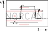
|
||
b
|
Problem: P share too small Solution: → Rotate Kp against F (fine adjustment) → P gain > |
|
|
DIL 14 |
ON |
|
|
DIL 15 |
OFF |
|
|
DIL 16 |
ON |
|
c
|
Problem: P share too large Solution: → Rotate Kp against 0 (fine adjustment) → Use DIL 14–16 to reduce the P gain according to the table |
|
d
|
Problem: P share correct Control deviation too large Solution: ➝ Increase the I gain share DIL 11 ON = I share = 0 DIL 12 ON = I share connected → Rotate Ki against F |
|
e
|
Problem: Time constant of the I share too low Solution: → Rotate Ki against F until control deviation and vibration are perfect → If Ki = F is not sufficient, the P share must also be reduced |
|
f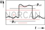
|
Problem: D share too low Solution: → Rotate KD against F → D share > |
|
|
DIL 8 |
ON |
|
|
DIL 9 |
OFF |
|
|
DIL 10 |
OFF |
|
Front plate

Block diagram with pin assignment
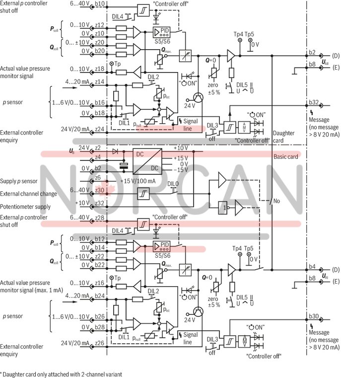
Amplifier – Valve

Pressure sensor connection: Example channel II

Principle of the channel selection

Adjustment table

DIL switch

HEXCODE switch
Example 2
Channel mode "separate outputs"

Example 1
Channel mode "joint output"

Dimensions in mm
