

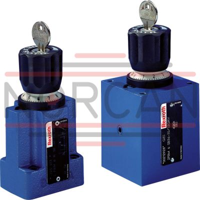
BOSCH REXROTH
R900205513
$1,105.84 USD
- BOSCH REXROTH
- Material:R900205513
- Model:2FRM6B36-3X/25QRV
Quantity in stock: 0
The Bosch Rexroth 2FRM6B36-3X/25QRV (R900205513) is a high-performance industrial hydraulic valve designed for precise flow control in hydraulic systems. This direct-actuated valve features a lockable rotary knob with scale, allowing for accurate adjustments to the flow rate according to the setting value. It includes an integrated check valve and does not require the closing of the pressure compensator for operation. This model is mechanically actuated and comes with a spool symbol indicating A to B and B to A porting, ensuring reliable control in both directions of flow. The 2FRM6B36-3X/25QRV valve is designed for subplate mounting with connection diagrams conforming to NFPA T..R D Size CETOP D and ISO standards, providing compatibility with widespread industry norms. The valve has a maximum pressure capacity and supports a maximum flow rate as specified by its design parameters. It offers multiple ports for connectivity and features FKM seals, making it suitable for use with various hydraulic fluids such as HL, HLP, HLPD, HVLP, HVLPD, HETG, HEES, HEPG, HFDU, and HFDR. Constructed to maintain constant flow regardless of external pressure and temperature changes, this Bosch Rexroth model is equipped with a durable housing and components that ensure long-term stability and performance. The presence of a pressure compensator downstream of the throttling point guarantees that the desired flow rate remains steady even when system pressures fluctuate. Overall, the Bosch Rexroth 2FRM6B36-3X/25QRV valve stands out for its robust construction, precise control capabilities, and adaptability to various industrial applications requiring reliable hydraulic flow regulation.
Size 6, A → B, B → A, mechanically actuated
Industrial hydraulic valve in a high performance range. Reliable control of the flow to setting value.
Unpacked Weight: 1 kg
General information
The flow control valve type 2 FRM is a 2-way flow control valve.
It is used for maintaining a constant flow, independent of pressure and temperature.
The valve basically consists of housing (1), rotary knob (2), orifice bush (3), pressure compensator (4) and an optional check valve.
Flow control valve type 2FRM 6 B…MV
(without external closing, without check valve)
The flow from channel A to channel B is throttled at the throttling point (5). The throttle cross-section is set by turning the rotary knob (2). To ensure a pressure-independent and constant flow in channel B, a pressure compensator (4) is fitted downstream of the throttling point (5).
The compression spring (6) presses the pressure compensator (4) downwards against its stop and keeps the pressure compensator (4) in the open position when there is no flow through the valve. When fluid flows through the valve, the pressure acting in channel A applies a force to the pressure compensator (4) via orifice (7).
The pressure compensator (4) moves into the controlled position until the forces balance. If the pressure in channel A rises, the pressure compensator (4) moves in the closing direction until the forces are balanced again. Due to this continuous compensation of the pressure compensator (4), a constant flow is obtained.
In order to control a flow through the valve in both directions, a rectifier sandwich plate type Z4S 6 may be fitted below this flow control valve.
Type 2FRM 6 B76-3X/.MV

| With check valve |
| Direct actuated |
| Without closing of the pressure compensator |
| Lockable rotary knob with scale |
| Maximum operating pressure 315 bar |
| Size 6 |
| Maximum flow 32 l/min |
| Component series 3X |
| Data Sheet | Download Data Sheet |
| Manual | Download Manual |
| Manual | Download Manual |
| Manual | Download Manual |
| Manual | Download Manual |
| Manual | Download Manual |
| Spool symbol | A → B, B → A |
| Max. pressure | 315 |
| Productgroup ID | 9,10,11,12,13,14 |
| Number of ports | 4 |
| Type of actuation | with mechanical actuation |
| Size | 6 |
| Max. flow | 25 |
| Type of connection | Subplate mounting |
| Connection diagram NFPA | NFPA T3.5.1 R2-2002 D03 |
| Size_CETOP | D03 |
| Connection diagram | ISO 6263-03-02-*-13 |
| Number of switching positions | 2 |
| Weight | 1 |
| Seals | FKM |
| Hydraulic fluid | HL,HLP,HLPD,HVLP,HVLPD,HETG,HEES,HEPG,HFDU,HFDR |
|
01 |
02 |
03 |
04 |
05 |
06 |
07 |
08 |
09 |
10 |
||
|
2FRM |
6 |
6 |
– |
3X |
/ |
V |
* |
|
01 |
2-way flow control valve |
2FRM |
|
02 |
Size 6 |
6 |
|
03 |
without closing of the pressure compensator |
B |
|
Adjustment type |
||
|
04 |
Lockable rotary knob with scale 1) |
3 |
|
Rotary knob with scale |
7 |
|
|
05 |
Zero position of the marking at port P |
6 |
|
06 |
Component series 30 ... 39 (30 ... 39: unchanged installation and connection dimensions) |
3X |
|
Flow (A → B) |
||
|
07 |
up to 0.2 l/min |
0,2Q |
|
up to 0.6 l/min |
0,6Q |
|
|
up to 1.5 l/min |
1,5Q |
|
|
up to 3.0 l/min |
3Q |
|
|
up to 6.0 l/min |
6Q |
|
|
up to 10 l/min |
10Q |
|
|
up to 16 l/min |
16Q |
|
|
up to 25.0 l/min |
25Q |
|
|
up to 32.0 l/min |
32Q |
|
|
08 |
With check valve |
R |
|
Without check valve |
M |
|
|
Seal material |
||
|
09 |
FKM seals (other seals upon request) |
V |
|
Observe compatibility of seals with hydraulic fluid used. |
||
|
10 |
Further details in the plain text |
* |
| 1) Key with material no. R900008158 is included in the scope of delivery. |
Preferred types and standard units are contained in the EPS (standard price list).
general
|
Size |
6 | |
|
Weight (approx.) |
kg |
1.3 |
|
Installation position |
any | |
|
Ambient temperature range |
°C |
-20 … +50 |
hydraulic
|
Size |
6 | ||||||||||
|
Maximum operating pressure 1) |
Anschluss A |
bar |
315 | ||||||||
|
Pressure differential Δp with free return flow B → A |
See characteristic curves | ||||||||||
|
Minimum pressure differential |
bar |
6 … 14 | |||||||||
|
Pressure stable (qV max) to Δp = 315 bar |
% |
± 2 | |||||||||
|
Maximum flow |
l/min |
0.2 | 0.6 | 1.5 | 3 | 6 | 10 | 16 | 25 | 32 | |
|
Minimum flow |
up to 100 bar |
l/min |
0.01 | 0.03 | 0.05 | 0.07 | 0.1 | 0.25 | |||
|
up to 315 bar |
l/min |
0.03 | 0.05 | 0.07 | 0.1 | 0.05 | |||||
|
Hydraulic fluid |
Mineral oil (HL, HLP) according to DIN 51524, other hydraulic fluids on request | ||||||||||
|
Hydraulic fluid temperature range |
°C |
-20 … +80 | |||||||||
|
Viscosity range |
mm²/s |
10 … 800 | |||||||||
|
Maximum admissible degree of contamination of the hydraulic fluid 2) |
Class 20/18/15 according to ISO 4406 (c) | ||||||||||
| 1) | In applications with rectifier sandwich plate up to 210 bar |
| 2) | The cleanliness classes specified for the components must be adhered to in hydraulic systems. Effective filtration prevents faults and simultaneously increases the life cycle of the components. For the selection of the filters, see www.boschrexroth.com/filter. |
For applications outside these parameters, please consult us!
(measured with HLP46, ϑOil = 40 ±5 °C)
Flow dependent on the scale setting (flow control A → B)


Δp-qV characteristic curve via check valve (B → A) orifice closed

pE-qV characteristic curve

Temperature dependency at Δp = 20 bar

|
simplified |
Detailed |
|
|
without check valve; without external closing Type 2FRM 6 B…MV |

|

|
|
with check valve; without external closing Type 2FRM 6 B…RV |

|

|
Subplate mounting – version “A” and “B”
Dimensions in mm

|
1 |
Adjustment type "3" (lockable rotary knob with scale) |
|
2 |
Adjustment type "7" (rotary knob with scale) |
|
3 |
Identical seal rings for ports A, B, P, and T |
|
4 |
Space required to remove the key |
|
5 |
Bore Ø3 mm at version "B" not bored (without external closing) |
|
6 |
Name plate |
|
7 |
Position of the marking at port P |
|
8 |
Porting pattern according to DIN 24340 form A |
Subplate mounting:
Valve mounting screws (separate order)
without rectifier sandwich plate4 hexagon socket head cap screws
ISO 4762 - M5 x 30 - 10.9-flZn-240h-L
at friction coefficient μtotal = 0.09 to 0.14,
Tightening torque MA = 7 Nm ± 10 %,
Material no. R913000316
with rectifier sandwich plate4 hexagon socket head cap screws
ISO 4762 - M5 x 70 - 10.9-flZn-240h-L
at friction coefficient μtotal = 0.09 to 0.14,
Tightening torque MA = 7 Nm ± 10 %,
Material no. R913000325
Subplates (separate order)
Type G 341/01 (G1/4)
Type G 342/01 (G3/8)
Type G 502/01 (G1/2)