


BOSCH REXROTH
R150221085
- BOSCH REXROTH
- Material:R150221085
- Model:FEM-E-C25X5RX3-4
Due to extremely high demand, please call 877-366-7226 for availability
The Bosch Rexroth FEM-E-C 25X5RX3-4 (R150221085) is a high-precision ball screw assembly designed to convert rotary motion into linear motion with minimal friction. This single nut with flange FEMEC is engineered for standard series applications and features a nominal diameter of 25mm and a lead of 5mm, ensuring precise and reliable operation. The ball diameter Dw and the number of ball track turns i are optimized for efficient load distribution and smooth movement. Constructed to align with mounting dimensions similar to DIN standards, the FEM-E-C 25X5RX3-4 offers versatility in installation with both flange type C and flange type B options available. It includes standard seals to protect against contaminants, along with standard axial clearance to accommodate thermal expansion and operational variances. The nut comes in various preload classes ranging from C0 to C5, allowing users to select the appropriate level of rigidity for their specific application needs. Tolerance grade T3 ensures compatibility with screws as per the product overview, while maintaining high precision in positioning tasks. This Bosch Rexroth ball screw assembly operates effectively within a temperature range of -10°C to +100°C, capable of sustaining continuous use at these temperatures while tolerating temporary peaks up to 120°C on the outer shell of the nut. It boasts an impressive dynamic load capacity Cdyn and static load rating C0 that are valid for tolerance grades T3 and T5; other grades may require a correction factor as noted in technical data sections. With its robust design, it can achieve maximum permissible linear speeds (vmax), ensuring efficient operation in demanding environments. The product's weight is meticulously calculated to provide stability without compromising performance. Suitable for various industrial applications, this ball screw assembly represents Bosch Rexroth's commitment to precision engineering and reliability.
| Mounting dimensions similar to DIN 69051, Part 5 flange type C (flange type B available). |
| With seals |
| With left-hand version in some cases |
| Preload class: C0, C00, C1, C2, C3 |
| Tolerance grade: T3 (for sizes as per the product overview for screws, see general technical notes and information, “Product description”), T5, T7, T9 |
| Data Sheet | Download Data Sheet |
| 3D CAD | Download 3D CAD |
| 3D CAD | Download 3D CAD |
| Manual | Download Manual |
| Manual | Download Manual |
| Manual | Download Manual |
| Manual | Download Manual |
| Manual | Download Manual |
| Size D5 | 62 |
| Size L with tolerance | 45 mm |
| Bearing temperature max | |
| Nut type | FEM-E-C single nut with flange |
| Series | Standard series |
| Bearing temperature min | |
| Productgroup ID | 17 |
| Nut or screw | Screw drive nut |
| Screw drive version (drive type) | Ball screw assembly |
| Maximum operating temperature | |
| Footnote dynamic load capacity C | The load capacities are valid for tolerance grade T3 and T5 only. For other tolerance grades, please take into account the correction factor fac (see General Technical Notes and Information "Technical Data", Technical Notes). |
| Bearing temperature | -15 °C ... +80 °C |
| Category | A |
| Minimum operating temperature | |
| Size L4 | 10 |
| Size D6 | 51 |
| Size L3 | 12 |
| Size L9 | 55 |
| Size D7 | 6.6 |
| Size L10 | 33 |
| Operating temperature | -10 °C ... +80 °C |
| Maximum permissible linear speed vmax (m/min) | 30 |
| Lead | 5 |
| Footnote static load capacity C0 | The load capacities are valid for tolerance grade T3 and T5 only. For other tolerance grades, please take into account the correction factor fac (see General Technical Notes and Information "Technical Data", Technical Notes). |
| Hole pattern | BB2 |
| Static load rating C0 | 27200 |
| Size Sx | 4 |
| Footnote permissible operating temperature (min...max) | Ball screw assemblies permit operation at continuous temperatures of up to 80 °C with temporary peaks of 100 °C, measurements taken on the outer shell of the nut in each case. |
| Size D1 g6 | 40 |
| Dynamic load capacity C | 19100 |
| Size d1 | 24 |
| Size L | 45 |
| Size d2 | 21.9 |
| Footnote operating temperature max. | Ball screw assemblies permit operation at continuous temperatures of up to 80°C with temporary peaks of 100°C, measurements taken on the outer shell of the nut in each case. |
| Note: Maximum permissible speed vmax | See "Characteristic speed d0 • n" (section Technical notes) and "Critical speed ncr" (section Calculation and examples) |
| Weight | 0.42 |
| Nominal size | 25 x 5R x 3 - 4 |
Technical data for nuts
|
Size |
C |
C0 |
vmax |
Mass |
|
d0 x P x Dw - i |
N |
N |
m/min |
kg |
| 16 x 5R x 3 - 4 | 14800 1) | 16100 1) | 30 2) | 0.19 |
| 16 x 10R x 3 - 3 | 11500 1) | 12300 1) | 60 2) | 0.21 |
| 16 x 16R x 3 - 3 | 11200 1) | 12000 1) | 96 2) | 0.26 |
| 20 x 5R x 3 - 4 | 17200 1) | 21500 1) | 30 2) | 0.31 |
| 20 x 10R x 3 - 4 | 16900 1) | 21300 1) | 60 2) | 0.4 |
| 20 x 20R x 3,5 - 3 | 16000 1) | 18800 1) | 120 2) | 0.49 |
| 25 x 5R x 3 - 4 | 19100 1) | 27200 1) | 30 2) | 0.36 |
| 25 x 10R x 3 - 4 | 18800 1) | 27000 1) | 60 2) | 0.47 |
| 25 x 25R x 3,5 - 3 | 17600 1) | 23300 1) | 150 2) | 0.63 |
| 32 x 5R x 3,5 - 4 | 25900 1) | 40000 1) | 23 2) | 0.62 |
| 32 x 10R x 3,969 - 5 | 38000 1) | 58300 1) | 47 2) | 0.84 |
| 32 x 20R x 3,969 - 3 | 23600 1) | 33700 1) | 94 2) | 0.9 |
| 32 x 32R x 3,969 - 3 | 23400 1) | 34000 1) | 150 2) | 1.21 |
| 40 x 5R x 3,5 - 5 | 34900 1) | 64100 1) | 19 2) | 1.03 |
| 40 x 10R x 6 - 4 | 60000 1) | 86400 1) | 38 2) | 1.19 |
| 40 x 10R x 6 - 6 | 86500 1) | 132200 1) | 1.49 | |
| 40 x 12R x 6 - 4 | 59900 1) | 86200 1) | 45 2) | 1.27 |
| 40 x 16R x 6 - 4 | 59600 1) | 85900 1) | 60 2) | 1.51 |
| 40 x 20R x 6 - 3 | 45500 1) | 62800 1) | 75 2) | 1.44 |
| 40 x 25R x 6 - 4 | 56900 1) | 85800 1) | 93 2) | 1.91 |
| 40 x 30R x 6 - 4 | 56300 1) | 85100 1) | 112 2) | 2.21 |
| 40 x 40R x 6 - 3 | 44400 1) | 62300 1) | 150 2) | 2.16 |
| 50 x 5R x 3,5 - 5 | 38400 1) | 81300 1) | 15 2) | 1.39 |
| 50 x 10R x 6 - 6 | 95600 1) | 166500 1) | 30 2) | 2.14 |
| 50 x 12R x 6 - 6 | 95500 1) | 166400 1) | 36 2) | 2.38 |
| 50 x 16R x 6 - 6 | 95300 1) | 166000 1) | 48 2) | 2.75 |
| 50 x 20R x 6,5 - 5 | 90800 1) | 149700 1) | 60 2) | 2.73 |
| 50 x 30R x 6,5 - 4 | 71300 1) | 118800 1) | 90 2) | 3.12 |
| 50 x 40R x 6,5 - 3 | 55800 1) | 85900 1) | 120 2) | 3.04 |
| 63 x 10R x 6 - 6 | 106600 1) | 214300 1) | 24 2) | 2.56 |
| 63 x 20R x 6,5 - 5 | 100700 1) | 190300 1) | 48 2) | 4.51 |
| 63 x 40R x 6,5 - 3 | 64100 1) | 114100 1) | 95 2) | 5.04 |
| 80 x 10R x 6,5 - 6 | 130100 1) | 291700 1) | 19 2) | 3.4 |
| 80 x 20R x 12,7 - 6 | 315200 1) | 534200 1) | 30 2) | 10.2 |
| 16 x 5L x 3 - 4 | 14800 1) | 16100 1) | 0.19 | |
| 20 x 5L x 3 - 4 | 17200 1) | 21500 1) | 0.31 | |
| 25 x 5L x 3 - 4 | 19100 1) | 27200 1) | 0.36 | |
| 32 x 5L x 3,5 - 4 | 25900 1) | 40000 1) | 23 2) | 0.62 |
| 40 x 5L x 3,5 - 5 | 34900 1) | 64100 1) | 19 2) | 1.03 |
| 40 x 10L x 6 - 4 | 60000 1) | 86400 1) | 38 2) | 1.19 |
| 1) | The load ratings are valid for tolerance grades T3 and T5 only. For other tolerance grades, please take into account the correction factor fac (see General Technical Notes and Information "Technical Data", Technical Notes). |
| 2) | See "characteristic speed d0 • n" (section Technical notes) and "critical speed n"cr" (section Calculation and examples) |
Operating conditions
|
Size |
Admissible operating temperature (min ... max) 1) |
Admissible storage temperature (min ... max) |
|
d0 x P x Dw - i |
||
| 16 x 5R x 3 - 4 | -10 °C ... +80 °C | -15 °C ... +80 °C |
| 16 x 10R x 3 - 3 | ||
| 16 x 16R x 3 - 3 | ||
| 20 x 5R x 3 - 4 | ||
| 20 x 10R x 3 - 4 | ||
| 20 x 20R x 3,5 - 3 | ||
| 25 x 5R x 3 - 4 | ||
| 25 x 10R x 3 - 4 | ||
| 25 x 25R x 3,5 - 3 | ||
| 32 x 5R x 3,5 - 4 | ||
| 32 x 10R x 3,969 - 5 | ||
| 32 x 20R x 3,969 - 3 | ||
| 32 x 32R x 3,969 - 3 | ||
| 40 x 5R x 3,5 - 5 | ||
| 40 x 10R x 6 - 4 | ||
| 40 x 10R x 6 - 6 | ||
| 40 x 12R x 6 - 4 | ||
| 40 x 16R x 6 - 4 | ||
| 40 x 20R x 6 - 3 | ||
| 40 x 25R x 6 - 4 | ||
| 40 x 30R x 6 - 4 | ||
| 40 x 40R x 6 - 3 | ||
| 50 x 5R x 3,5 - 5 | ||
| 50 x 10R x 6 - 6 | ||
| 50 x 12R x 6 - 6 | ||
| 50 x 16R x 6 - 6 | ||
| 50 x 20R x 6,5 - 5 | ||
| 50 x 30R x 6,5 - 4 | ||
| 50 x 40R x 6,5 - 3 | ||
| 63 x 10R x 6 - 6 | ||
| 63 x 20R x 6,5 - 5 | ||
| 63 x 40R x 6,5 - 3 | ||
| 80 x 10R x 6,5 - 6 | ||
| 80 x 20R x 12,7 - 6 | ||
| 16 x 5L x 3 - 4 | ||
| 20 x 5L x 3 - 4 | ||
| 25 x 5L x 3 - 4 | ||
| 32 x 5L x 3,5 - 4 | ||
| 40 x 5L x 3,5 - 5 | ||
| 40 x 10L x 6 - 4 |
| 1) | Ball screw assemblies are suitable for continuous operation at temperatures up to 80 °C with temporary peaks of 100 °C (measurements taken on the outer shell of the nut). |
Legend
|
Symbol |
Description |
Unit |
|
d0 |
Nominal diameter |
mm |
|
P |
Lead (R = right-hand, L = left-hand) |
|
|
Dw |
Ball diameter |
mm |
|
i |
Number of ball track turns |
|
|
C |
Dynamic load capacity |
N |
|
C0 |
Static load capacity |
N |
|
vmax |
Maximum permissible speed |
m/min |
Technical notes
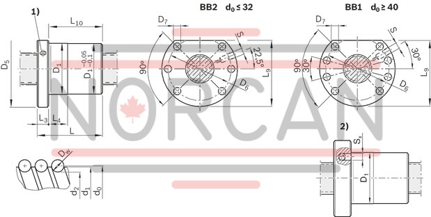
| 1) | Lube port at flange center (lube port machining: Flat surface L3 ≤ 15 mm, countersink L3 > 15 mm) |
| 2) | Nut rework: Axial lube port |
Dimensions
|
Size |
d1 |
d2 |
D1 |
D5 |
Hole pattern |
D6 |
D7 |
L |
L3 |
L4 |
L9 1) |
L10 |
S 2) |
Sx |
|
d0 x P x Dw - i |
g6 |
|||||||||||||
|
mm |
mm |
mm |
mm |
mm |
mm |
mm |
mm |
mm |
mm |
mm |
mm |
mm |
||
| 16 x 5R x 3 - 4 | 15 | 12.9 | 28 | 48 | BB2 | 38 | 5.5 | 38 | 12 | 10 | 44 | 26 | M6 | 4 |
| 16 x 10R x 3 - 3 | 45 | 16 | 33 | |||||||||||
| 16 x 16R x 3 - 3 | 61 | 20 | 49 | |||||||||||
| 20 x 5R x 3 - 4 | 19 | 16.9 | 36 | 58 | 47 | 6.6 | 40 | 10 | 51 | 28 | ||||
| 20 x 10R x 3 - 4 | 60 | 16 | 48 | |||||||||||
| 20 x 20R x 3,5 - 3 | 16.7 | 77 | 25 | 65 | ||||||||||
| 25 x 5R x 3 - 4 | 24 | 21.9 | 40 | 62 | 51 | 45 | 10 | 55 | 33 | |||||
| 25 x 10R x 3 - 4 | 64 | 16 | 52 | |||||||||||
| 25 x 25R x 3,5 - 3 | 21.4 | 95 | 30 | 83 | ||||||||||
| 32 x 5R x 3,5 - 4 | 31 | 28.4 | 50 | 80 | 65 | 9 | 48 | 13 | 10 | 71 | 35 | |||
| 32 x 10R x 3,969 - 5 | 27.9 | 77 | 16 | 64 | ||||||||||
| 32 x 20R x 3,969 - 3 | 84 | 25 | 71 | |||||||||||
| 32 x 32R x 3,969 - 3 | 120 | 40 | 107 | |||||||||||
| 40 x 5R x 3,5 - 5 | 39 | 36.4 | 63 | 93 | BB1 | 78 | 54 | 15 | 10 | 81.5 | 39 | M8x1 | 5 | |
| 40 x 10R x 6 - 4 | 38 | 33.8 | 70 | 16 | 55 | |||||||||
| 40 x 10R x 6 - 6 | 90 | 75 | ||||||||||||
| 40 x 12R x 6 - 4 | 75 | 25 | 60 | |||||||||||
| 40 x 16R x 6 - 4 | 90 | 75 | ||||||||||||
| 40 x 20R x 6 - 3 | 88 | 73 | ||||||||||||
| 40 x 25R x 6 - 4 | 127 | 30 | 112 | |||||||||||
| 40 x 30R x 6 - 4 | 145 | 35 | 130 | |||||||||||
| 40 x 40R x 6 - 3 | 142 | 45 | 127 | |||||||||||
| 50 x 5R x 3,5 - 5 | 49 | 46.4 | 75 | 110 | 93 | 11 | 54 | 10 | 97.5 | 39 | ||||
| 50 x 10R x 6 - 6 | 48 | 43.8 | 90 | 18 | 16 | 72 | ||||||||
| 50 x 12R x 6 - 6 | 105 | 25 | 87 | |||||||||||
| 50 x 16R x 6 - 6 | 128 | 110 | ||||||||||||
| 50 x 20R x 6,5 - 5 | 43.4 | 132 | 114 | |||||||||||
| 50 x 30R x 6,5 - 4 | 151 | 35 | 133 | |||||||||||
| 50 x 40R x 6,5 - 3 | 149 | 45 | 131 | |||||||||||
| 63 x 10R x 6 - 6 | 61 | 56.8 | 90 | 125 | 108 | 90 | 22 | 16 | 110 | 68 | ||||
| 63 x 20R x 6,5 - 5 | 56.4 | 95 | 135 | 115 | 13.5 | 132 | 25 | 117.5 | 110 | |||||
| 63 x 40R x 6,5 - 3 | 149 | 45 | 127 | |||||||||||
| 80 x 10R x 6,5 - 6 | 78 | 73.3 | 105 | 145 | 125 | 95 | 16 | 127.5 | 73 | |||||
| 80 x 20R x 12,7 - 6 | 76 | 67 | 125 | 165 | 145 | 170 | 25 | 25 | 147.5 | 145 | ||||
| 16 x 5L x 3 - 4 | 15 | 12.9 | 28 | 48 | BB2 | 38 | 5.5 | 38 | 12 | 10 | 44 | 26 | M6 | |
| 20 x 5L x 3 - 4 | 19 | 16.9 | 36 | 58 | 47 | 6.6 | 40 | 51 | 28 | |||||
| 25 x 5L x 3 - 4 | 24 | 21.9 | 40 | 62 | 51 | 45 | 55 | 33 | ||||||
| 32 x 5L x 3,5 - 4 | 31 | 28.4 | 50 | 80 | 65 | 9 | 48 | 13 | 71 | 35 | ||||
| 40 x 5L x 3,5 - 5 | 39 | 36.4 | 63 | 93 | BB1 | 78 | 54 | 15 | 81.5 | 39 | M8x1 | |||
| 40 x 10L x 6 - 4 | 38 | 33.8 | 70 | 16 | 55 |
| 1) | Flange type B (two flat surfaces) option available! |
| 2) | Lube port machining: Flat surface L3 ≤ 15 mm, countersink L3 > 15 mm. With left-hand lead the lube port position mirrors its position with right-hand lead! |
Legend
|
Symbol |
Description |
|
d0 |
Nominal diameter |
|
P |
Lead (R = right-hand, L = left-hand) |
|
Dw |
Ball diameter |
|
i |
Number of ball track turns |
Attention: When setting up applications, do not allow components to collide with the front lube unit.
Nut housing MGD
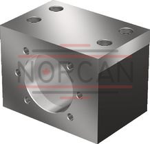
Nut housing MGD
Steel nut housings MGD are designed for FEM-E-C, FDM-E-C, SEM-E-C and FED-E-B nutsCatalog
Service
CAD data
Front lube unit – ball screw assembly
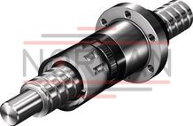
Front lube unit – ball screw assembly
Catalog
Service
Arrestor nut
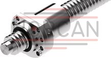
Arrestor nut
Catalog
Service
Required and supplementary documentation
For further instructions and information, please refer to the documentation for this product.
You can find PDF files of these documents on the Internet at www.boschrexroth.com/mediadirectory.
If you are unsure about using this product, please contact Bosch Rexroth.
Notes