

BOSCH REXROTH
R407999222
- BOSCH REXROTH
- Material:R407999222
- Model:R900999L21
Due to extremely high demand, please call 877-366-7226 for availability
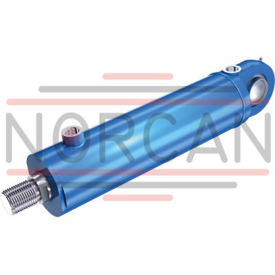
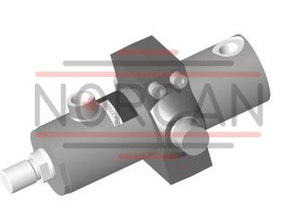
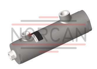
The Bosch Rexroth CDL2 SERIE 1X KONFIG (R407999222) is a robust hydraulic cylinder designed for demanding applications requiring a mill type design. This specific model allows for customization and online configuration, ensuring it meets the precise needs of its application. With a nominal pressure capacity of up to ... bar and a piston diameter of ... mm complemented by a piston rod diameter of ... mm, it can handle significant mechanical loads. The stroke length is configurable up to ... mm, catering to a wide range of motion requirements. The CDL2 series features an automated provision of configuration-specific dimensional drawings and 3D data, streamlining the design integration process for engineers and designers. It also boasts a service-oriented modular system that includes various types of mounting options, providing flexibility in system design and installation. The maximum pressure rating underscores its capability to operate reliably under high-pressure conditions. A product group ID is associated with this model for easy reference, and it has been subjected to static test pressure to ensure durability and performance reliability. For maintenance convenience, the CDL2 series offers bleeding without weight complications. The seals are available in NBR or FKM materials, catering to different environmental conditions and hydraulic fluid compatibility with standard types such as HL, HLP, HFDR. The short length of assembly feature facilitates compact machine designs without sacrificing performance. Bosch Rexroth's commitment to quality is evident in this hydraulic cylinder's construction and capabilities, making it suitable for various applications where precision movement and high-load handling are essential.
Nominal pressure 160 ... 250 bar, piston Ø 25 ... 200 mm, piston rod Ø 14 ... 125 mm, stroke length up to 3000 mm
Hydraulic cylinder in mill type design, configurable online, with piston rod on one side.
Automated provision of configuration-specific dimensional drawing and 3D data.
Unpacked Weight: 0.6 kg
| Service-oriented modular system |
| 4 types of mounting |
| Data Sheet | Download Data Sheet |
| Manual | Download Manual |
| Manual | Download Manual |
| Manual | Download Manual |
| Manual | Download Manual |
| Manual | Download Manual |
| Max. pressure | 160 |
| Productgroup ID | 9,10,11,12,13,14 |
| Static test pressure | 375 |
| Bleeding | without |
| Weight | 0.6 |
| Seals | NBR,FKM |
| Hydraulic fluid | HL,HLP,HFDR |
Ordering code
|
01 |
02 |
03 |
04 |
05 |
06 |
07 |
08 |
09 |
10 |
11 |
12 |
13 |
14 |
15 |
16 |
17 |
18 |
||||
|
CD |
L2 |
/ |
/ |
/ |
1X |
/ |
B |
1 |
1 |
C |
U |
W |
* |
|
Type |
||
|
01 |
Single rod cylinder |
CD |
|
02 |
Series L2 |
L2 |
|
Types of mounting |
||
|
03 |
Self-aligning clevis at cylinder base |
MP5 |
|
Round flange at the cylinder head |
MF31) |
|
|
Trunnion |
MT41;2) |
|
|
Without mounting |
M003) |
|
|
04 |
Piston Ø (ØAL) from 25 ... 200 mm; possible version see Technical data |
... |
|
05 |
Piston rod Ø (ØMM) with nominal pressure 160 bar: 14, 18, 22, 28, 36, 45, 56 and 70 mm possible; see Technical data |
... |
|
Piston rod Ø (ØMM) with nominal pressure 250 bar: 25, 32, 40, 50, 63, 80, 100 and 125 mm possible; see Technical data |
||
|
06 |
Stroke length in mm; observe admissible stroke lengths; see Project planning information |
... |
|
Design principle |
||
|
07 |
Head and base screwed in |
C3) |
|
Head screwed in, base welded |
D4) |
|
|
08 |
Component series 10 ... 19 (10 ... 19: unchanged installation and connection dimensions) |
1X |
|
Line connection / version |
||
|
09 |
Pipe thread according to ISO 228/1 |
B |
|
Line connection/position at cylinder head |
||
|
10 |
View to piston rod 
|
1 |
|
Line connection/position at cylinder base |
||
|
11 |
View to piston rod
|
1 |
|
Piston rod design |
||
|
12 |
Hard chromium-plated |
C |
|
Piston rod end |
||
|
13 |
Thread |
H4) |
|
Piston rod end “H” with mounted swivel head CGKD |
K4) |
|
|
With swivel head, cannot be disassembled |
F4;5) |
|
|
Internal thread |
E3) |
|
|
Piston rod end “E” with mounted swivel head CGKL |
L3) |
|
|
End position cushioning |
||
|
14 |
Without end position cushioning |
U |
|
Seal design |
||
|
15 |
Standard seal system (suitable for mineral oils HL, HLP) |
M |
|
Standard seal system FKM (for phosphate ester HFDR) |
V |
|
|
Option 1 |
||
|
16 |
Without option |
W |
|
Option 2 |
||
|
17 |
Without option |
W |
|
With piston rod extension “LY” in mm |
Y6) |
|
|
18 |
Further details in the plain text |
* |
| 1) | Only piston Ø (ØAL) 25 ... 125 mm |
| 2) | Trunnion position freely selectable. When ordering, always specify the dimension "XV/XU" in the plain text in mm (see order example) |
| 3) | Only piston Ø (ØAL) 25 ... 32 mm |
| 4) | Only piston Ø (ØAL) 40 ... 200 mm |
| 5) | Only MP5; MT4 |
| 6) |
When ordering, always specify the piston rod extension dimension "LY" in the plain text in mm (see order example) |
| Order example: | |
| CDL2MT4/100/56/200D1X/B11CHUMWY, LY = 20 mm, XV = 245 mm | |
| CDL2MF3/80/45/100D1X/B11CHUMWW |
general
|
Installation position |
Any | |
|
Ambient temperature range |
°C |
-20 … +80 |
|
Primer coat |
Gentian blue (RAL 5010) | |
|
Minimum layer thickness of the priming 1) |
µm |
40 |
| 1) |
Other colors upon request. With cylinders and attachment parts, the following surfaces are not primed or painted: ▶ All fit diameters to the customer’s side ▶ Sealing surfaces for line connection The unpainted surfaces are protected using a corrosion protection agent (MULTICOR LF 80). |
hydraulic
|
Piston rod Ø |
mm |
14 | 18 | 22 | 25 | 28 | 32 | 36 | 40 | 45 | 50 | 56 | 63 | 70 | 80 | 100 | 125 |
|
Nominal pressure 1) |
bar |
160 | 250 | 160 | 250 | 160 | 250 | 160 | 250 | 160 | 250 | 160 | 250 | ||||
|
Operating pressure, min. (without load) 2) (without load) 2) |
bar |
10 | |||||||||||||||
|
Static test pressure |
bar |
375 | |||||||||||||||
|
Hydraulic fluid temperature range |
°C |
-20 … +80 | |||||||||||||||
|
Operating viscosity range |
mm²/s |
12 … 380 | |||||||||||||||
|
Optimum viscosity at operating temperature |
mm²/s |
20 … 100 | |||||||||||||||
|
Maximum admissible degree of contamination of the hydraulic fluid, cleanliness class according to ISO 4406 (c) 3) |
Class 20/18/15 according to ISO 4406 (c) | ||||||||||||||||
|
Maximum stroke velocity (depending on line connection) |
m/s |
0.5 | |||||||||||||||
| 1) | The cylinders of this series have been designed for 2 million load cycles at their nominal pressure. Higher operating pressures upon request. If there are extreme loads, such as high sequence cycles, the suitability of mounting elements and threaded piston rod connections for the application must be checked due to standardized geometries. |
| 2) | A minimum operating pressure is required in order to guarantee good functioning of the cylinder. Without load, a minimum pressure is recommend, for lower pressures, please contact us. |
| 3) | The cleanliness classes specified for the components must be adhered to in hydraulic systems. Effective filtration prevents faults and simultaneously increases the life cycle of the components. For the selection of the filters, see www.boschrexroth.com/filter. |
|
Hydraulic fluid |
Classification |
Suitable sealing materials |
Standards |
|
|
Mineral oil |
HL, HLP |
FKM, NBR |
DIN 51524 |
|
|
Flame-resistant |
Water-free |
HFDR |
FKM |
ISO 12922 |
Weight
|
Piston |
Piston rod |
with 0 mm stroke length |
per 100 mm stroke length |
|||
|
ØAL |
ØMM |
MP5 |
MF3 |
MT4 |
M00 |
|
|
mm |
kg |
kg |
kg |
kg |
kg |
|
| 25 | 14 mm / - | 1 | 1 | 1 | 1 | 0.4 |
| 32 | 18 mm / - | 2 | 2 | 2 | 2 | 0.6 |
| 40 | 22 mm / - | 2 | 3 | 3 | - | 0.9 |
| 25 mm / - | 2 | 4 | 4 | - | 1.1 | |
| 50 | 28 mm / - | 3 | 4 | 5 | - | 1.2 |
| 32 mm / - | 4 | 5 | 7 | - | 1.5 | |
| 63 | 36 mm / - | 5 | 7 | 9 | - | 1.8 |
| 40 mm / - | 6 | 9 | 12 | - | 2.3 | |
| 80 | 45 mm / - | 9 | 13 | 15 | - | 2.9 |
| 50 mm / - | 11 | 15 | 20 | - | 3.8 | |
| 100 | 56 mm / - | 15 | 20 | 26 | - | 4.6 |
| 63 mm / - | 19 | 26 | 36 | - | 6 | |
| 125 | 70 mm / - | 29 | 35 | 46 | - | 7.2 |
| 80 mm / - | 38 | 43 | 67 | - | 10.1 | |
| 160 | 100 mm / - | 67 | - | - | - | 15.1 |
| 200 | 125 mm / - | 110 | - | - | - | 22 |
Life cycle:
Rexroth cylinders correspond to the reliability recommendations for industrial applications. ≥ 10,000,000 Double strokes in idle continuous operation or 3,000 km piston travel at 70 % of the nominal pressure, without load on the piston rod, with a maximum velocity of 0.5 m/s, with a failure rate of less than 5 %.

Notices:
Boundary and application conditions
The mechanical alignment of the movement axis and thus the mounting points of hydraulic cylinder and piston rod must be ensured. Lateral forces on the guides of piston rod and piston are to be avoided. It may be necessary to consider the own weight of the hydraulic cylinder (MP5 or MT4) or the piston rod. The kinking length/kinking load of the piston rod and/or the hydraulic cylinder must be observed. The maximum admissible operating pressure must be complied with in any operating state of the hydraulic cylinder. Possible pressure intensification resulting from the area ratio of annulus area to piston area and possible throttling points are to be observed. Detrimental environmental influences, like e. g. aggressive finest particles, vapors, high temperatures, etc. as well as contamination and deterioration of the hydraulic fluid are to be avoided.
Standards:
Rexroth standard; main dimensions like piston Ø (ØAL) and piston rod Ø (ØMM) correspond to ISO 3320.
Acceptance:
Every cylinder is tested according to Rexroth standard and complying with ISO10100:2001.
Safety instructions:
For assembly, commissioning and maintenance of hydraulic cylinders, observe the operating instructions 07100-B! Service and repair work has to be performed by Bosch Rexroth AG or by personnel especially trained for this purpose. No warranty is accepted for damage as a consequence of assembly, maintenance or repair work not performed by Bosch Rexroth AG.
Check lists for hydraulic cylinders:
Cylinders the characteristics and/or application parameters of which deviate from the values specified in the data sheet can only be offered as a special version upon request. For offers, the variations of the characteristics and/or application parameters must be described in the check lists for hydraulic cylinders (07200).
This list does not claim to be complete. In case of questions regarding the compatibility with the medium or exceedance of the boundary or application conditions, please contact us.
Project planning software ICS (Interactive Catalog System)
The ICS (Interactive Catalog System) is a selection and project planning help for hydraulic cylinders. The ICS allows designers for machines and systems to quickly and reliably find the perfect hydraulic cylinder solution through logic-guided type key enquiries. This software helps to solve design and project planning tasks more quickly and efficiently. After having been guided through the product selection, the user quickly and reliably gets the exact technical data of the selected component as well as 2D and 3D CAD data in the correct file format for all common CAD systems.
This allows users to reduce costs while increasing their competitiveness.
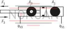
Diameter, areas, forces, flow (for operating pressure up to 160 bar)
|
Piston |
Piston rod at nominal pressure 160 bar |
Area ratio |
Areas |
Force at 160 bar |
Flow at 0.1 m/s |
Maximum available stroke length |
|||
|
Piston |
Ring |
Pressure |
Traction |
Off |
On |
||||
|
ØAL |
ØMM |
φ A1/A3 |
A1 |
A3 |
F1 |
F3 |
qV1 |
qV3 |
|
|
mm |
cm² |
cm² |
kN |
kN |
l/min |
l/min |
mm |
||
| 25 | 14 mm / - | 1.46 | 4.91 | 3.37 | 7.85 1) | 5.39 | 2.94 2) | 2.02 | 600 |
| 32 | 18 mm / - | 1.46 | 8.04 | 5.5 | 12.86 1) | 8.79 | 4.82 2) | 3.3 | 800 |
| 40 | 22 mm / - | 1.43 | 12.56 | 8.76 | 20.1 1) | 14.02 | 7.54 2) | 5.26 | 1000 |
| 50 | 28 mm / - | 1.46 | 19.63 | 13.47 | 31.4 1) | 21.55 | 11.78 2) | 8.08 | 1200 |
| 63 | 36 mm / - | 1.49 | 31.16 | 20.98 | 49.85 1) | 33.57 | 18.69 2) | 12.59 | 1400 |
| 80 | 45 mm / - | 1.46 | 50.24 | 34.34 | 80.38 1) | 54.95 | 30.14 2) | 20.61 | 1700 |
| 100 | 56 mm / - | 1.46 | 78.5 | 53.88 | 125.6 1) | 86.21 | 47.1 2) | 32.33 | 2000 |
| 125 | 70 mm / - | 1.46 | 122.66 | 84.19 | 196.25 1) | 134.71 | 73.59 2) | 50.51 | 2300 |
| 1) | Theoretical static cylinder force (without consideration of the efficiency and admissible load for attachment parts such as swivel heads, plates, or valves, etc.) |
| 2) | Stroke velocity |
Diameters, areas, forces, flow (for operating pressure up to 250 bar)
|
Piston |
Piston rod at nominal pressure 250 bar |
Area ratio |
Areas |
Force at 250 bar |
Flow at 0.1 m/s |
Maximum available stroke length |
|||
|
Piston |
Ring |
Pressure |
Traction |
Off |
On |
||||
|
ØAL |
ØMM |
φ A1/A3 |
A1 |
A3 |
F1 |
F3 |
qV1 |
qV3 |
|
|
mm |
cm² |
cm² |
kN |
kN |
l/min |
l/min |
mm |
||
| 40 | 25 mm / - | 1.64 | 12.56 | 7.65 | 31.4 1) | 19.13 | 7.54 2) | 4.59 | 1000 |
| 50 | 32 mm / - | 1.69 | 19.63 | 11.59 | 49.06 1) | 28.97 | 11.78 2) | 6.95 | 1200 |
| 63 | 40 mm / - | 1.68 | 31.16 | 18.6 | 77.89 1) | 46.49 | 18.69 2) | 11.16 | 1400 |
| 80 | 50 mm / - | 1.64 | 50.24 | 30.62 | 125.6 1) | 76.54 | 30.14 2) | 18.37 | 1700 |
| 100 | 63 mm / - | 1.66 | 78.5 | 47.34 | 196.25 1) | 118.36 | 47.1 2) | 28.41 | 2000 |
| 125 | 80 mm / - | 1.69 | 122.66 | 72.42 | 306.64 1) | 181.04 | 73.59 2) | 43.45 | 2300 |
| 160 | 100 mm / - | 1.64 | 200.96 | 122.46 | 502.4 1) | 306.15 | 120.58 2) | 73.48 | 2600 |
| 200 | 125 mm / - | 1.64 | 314 | 191.34 | 785 1) | 478.36 | 188.4 2) | 114.81 | 3000 |
| 1) | Theoretical static cylinder force (without consideration of the efficiency and admissible load for attachment parts such as swivel heads, plates, or valves, etc.) |
| 2) | Stroke velocity |
Tolerances
|
Installation dimensions |
WC |
XO/XF1) |
XV/XU |
|
|
Mounting type |
MF3 |
MP5 |
MT4 |
|
|
Stroke length in mm |
Tolerances in mm |
Stroke tolerances in mm |
||
|
≤ 1.250 |
±3 |
±2 |
±2 |
+2,5 |
|
< 1.250 … ≤ 3.000 |
±4 |
±3 |
±4 |
±4 |
| 1) | Including stroke length |
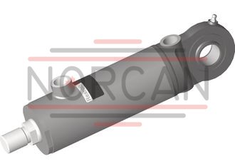
Type of mounting MP5: Self-aligning clevis at cylinder base
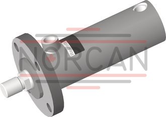
Type of mounting MF3: Round flange at the cylinder head
Type of mounting MT4: Trunnion
Type of mounting M00: no mounting
For applications outside these parameters, please consult us!
Type of mounting MP5: Self-aligning clevis at cylinder base
Piston Ø (ØAL) 25 … 32 mm
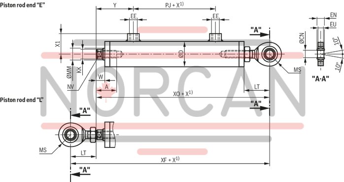
| 1) | X = stroke length |
Piston Ø (ØAL) 40 … 200 mm
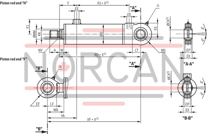
| 1) | X = stroke length |
| 2) | Related bolt Ø j6 |
| 3) | Lubricating nipple, cone head form A according to DIN 71412 |
Dimensions: type of mounting MP5 (for operating pressure up to 160 bar)
|
ØAL |
ØMM at nominal pressure 160 bar |
KK |
A |
NV |
W |
WA |
ØD |
Y |
YA |
PJ |
XO |
XF |
EE |
X1 |
X3 |
LT |
LF |
MS |
ØCX |
EX |
EP max. |
EF |
ØCN |
EN |
EU max. |
|||||||
|
mm |
mm |
mm |
mm |
mm |
mm |
mm |
mm |
mm |
mm |
mm |
mm |
mm |
mm |
mm |
mm |
mm |
mm |
mm |
mm |
mm |
mm |
mm |
mm |
mm |
mm |
mm |
mm |
|||||
| 25 | 14 mm / - | M10 | 26 | 12 | 10 | - | 32 | 44 | - | 26 | 131 | 158 | G1/8 | 24.5 | ± 1 | - | - | 27 | - | 145 | ± 2 | - |
- - |
- | - | - | - | 10 |
0 - 0.008 |
9 |
h12 |
7.5 |
| 32 | 18 mm / - | M12 | 28 | 15 | 11 | - | 40 | 48 | - | 31 | 148 | 180 | G1/4 | 33 | ± 1 | - | - | 32 | - | 17 | ± 2 | - |
- - |
- | - | - | - | 12 |
0 - 0.008 |
10 |
h12 |
8.5 |
| 40 | 22 mm / - | M16 x 1.5 | 22 | 17 | 13 | 44 | 50 | 60 | 91 | 50 | 140 | 171 | G1/4 | 39 | ± 1 | 29 | ± 1 | 24 | 23 | 28 | ± 2 | 20 |
H7 |
20 | 16 | 28 | ± 2 | - |
- - |
- |
- - |
- |
| 50 | 28 mm / - | M20 x 1.5 | 28 | 22 | 13 | 50 | 60 | 62 | 99 | 57 | 157 | 194 | G3/8 | 45 | ± 1 | 33 | ± 1 | 31 | 29 | 33 | ± 2 | 25 |
H7 |
25 | 20 | 33 | ± 2 | - |
- - |
- |
- - |
- |
| 63 | 36 mm / - | M27 x 2 | 36 | 28 | 14 | 63 | 75 | 68 | 117 | 69 | 182 | 231 | G1/2 | 55 | ± 1 | 40 | ± 1 | 38 | 34 | 42 | ± 2 | 32 |
H7 |
32 | 22 | 42 | ± 2 | - |
- - |
- |
- - |
- |
| 80 | 45 mm / - | M33 x 2 | 45 | 36 | 16 | 76 | 95 | 84 | 144 | 76 | 208 | 268 | G1/2 | 65 | ± 1 | 53 | ± 1 | 46 | 44 | 51 | ± 2 | 40 |
H7 |
40 | 26 | 51 | ± 2 | - |
- - |
- |
- - |
- |
| 100 | 56 mm / - | M42 x 2 | 56 | 46 | 18 | 88 | 120 | 90 | 160 | 85 | 227 | 297 | G3/4 | 80 | ± 1 | 63 | ± 1 | 54 | 50 | 61 | ± 2 | 50 |
H7 |
50 | 34 | 61 | ± 2 | - |
- - |
- |
- - |
- |
| 125 | 70 mm / - | M48 x 2 | 63 | 60 | 20 | 106 | 150 | 99 | 185 | 93 | 259 | 345 | G3/4 | 95 | ± 1 | 78 | ± 1 | 65 | 63 | 76 | ± 2 | 63 |
H7 |
63 | 42 | 76 | ± 2 | - |
- - |
- |
- - |
- |
Dimensions: type of mounting MP5 (for operating pressure up to 250 bar)
|
ØAL |
ØMM at nominal pressure 250 bar |
KK |
A |
NV |
W |
WA |
ØD |
Y |
YA |
PJ |
XO |
XF |
EE |
X1 |
X3 |
LT |
LF |
MS |
ØCX |
EX |
EP max. |
EF |
||||||
|
mm |
mm |
mm |
mm |
mm |
mm |
mm |
mm |
mm |
mm |
mm |
mm |
mm |
mm |
mm |
mm |
mm |
mm |
mm |
mm |
mm |
mm |
mm |
mm |
|||||
| 40 | 25 mm / - | M20 x 1.5 | 28 | 19 | 15 | 41 | 52 | 62 | 88 | 54 | 147 | 173 | G1/4 | 46 | ± 1 | 30 | ± 1 | 29 | 29 | 31 | ± 2 | 25 |
H7 |
25 |
h12 |
20 | 33 | ± 2 |
| 50 | 32 mm / - | M27 x 2 | 36 | 27 | 15 | 52 | 62 | 64 | 101 | 65 | 167 | 204 | G3/8 | 52 | ± 1 | 37 | ± 1 | 37 | 34 | 39 | ± 2 | 32 |
H7 |
32 |
h12 |
22 | 42 | ± 2 |
| 63 | 40 mm / - | M33 x 2 | 45 | 32 | 17 | 64 | 78 | 71 | 118 | 72 | 192 | 239 | G1/2 | 65 | ± 1 | 44 | ± 1 | 48 | 44 | 48 | ± 2 | 40 |
H7 |
40 |
h12 |
26 | 51 | ± 2 |
| 80 | 50 mm / - | M42 x 2 | 56 | 41 | 19 | 74 | 100 | 84 | 139 | 81 | 222 | 277 | G1/2 | 76 | ± 1 | 57 | ± 1 | 57 | 50 | 60 | ± 2 | 50 |
H7 |
50 |
h12 |
34 | 61 | ± 2 |
| 100 | 63 mm / - | M48 x 2 | 63 | 50 | 19 | 90 | 125 | 91 | 162 | 93 | 256 | 327 | G3/4 | 91 | ± 1 | 70 | ± 1 | 73 | 63 | 73 | ± 2 | 63 |
H7 |
63 |
h12 |
42 | 76 | ± 2 |
| 125 | 80 mm / - | M64 x 3 | 85 | 65 | 22 | 112 | 160 | 105 | 195 | 113 | 307 | 397 | G3/4 | 109 | ± 1 | 88 | ± 1 | 90 | 80 | 92 | ± 2 | 80 |
H7 |
80 |
h12 |
52 | 92 | ± 2 |
| 160 | 100 mm / - | M80 x 3 | 95 | 85 | 30 | 118 | 200 | 124 | 212 | 120 | 390 | 478 | G1 | 136 | ± 1 | 97 | ± 1 | 120 | - | 110 | ± 2 | 100 |
H7 |
100 |
h12 |
72 | 110 | ± 2 |
| 200 | 125 mm / - | M100 x 3 | 112 | 110 | 35 | 143 | 245 | 139 | 247 | 124 | 434 | 542 | G1 | 158 | ± 1 | 120 | ± 1 | 145 | - | 130 | ± 2 | 125 |
H7 |
125 |
h12 |
92 | 130 | ± 2 |
Type of mounting MF3: Round flange at the cylinder head
Piston Ø (ØAL) 25 … 32 mm
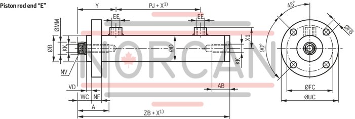
| 1) | X = stroke length |
Piston Ø (ØAL) 40 … 200 mm
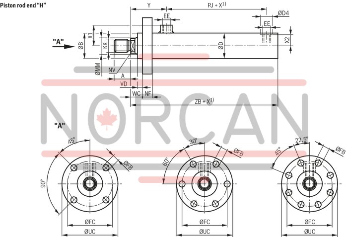
| 1) | X = stroke length |
Dimensions: type of mounting MF3 (for operating pressure up to 160 bar)
|
ØAL |
ØMM at nominal pressure 160 bar |
KK |
A |
AB |
NV |
ØB |
VD |
WC |
NF |
ØD |
Y |
PJ |
EE |
ØD4 |
X1 |
X2 |
ZB |
ØFB |
ØFC |
ØUC max. |
Number of mounting bores |
||||
|
mm |
mm |
mm |
mm |
mm |
mm |
mm |
mm |
mm |
mm |
mm |
mm |
mm |
mm |
mm |
mm |
mm |
mm |
mm |
mm |
mm |
|||||
| 25 | 14 mm / - | M10 | 26 | 21 | 12 | 32 | ± 0.3 | 6 | 16 | 12 | 32 | 44 | 26 | G1/8 | - | 245 | ± 1 | - | - | 104 | 66 |
H13 |
55 | 68 | 4 |
| 32 | 18 mm / - | M12 | 28 | 25 | 15 | 40 | ± 0.3 | 6 | 17 | 12 | 40 | 48 | 31 | G1/4 | - | 33 | ± 1 | - | - | 116 | 9 |
H13 |
65 | 78 | 4 |
| 40 | 22 mm / - | M16 x 1.5 | 22 | - | 17 | 50 | ± 0.3 | 7 | 20 | 14 | 50 | 60 | 50 | G1/4 | 23 | 39 | ± 1 | 22 | ± 1 | 124 | 11 |
H13 |
85 | 108 | 4 |
| 50 | 28 mm / - | M20 x 1.5 | 28 | - | 22 | 60 | ± 0.3 | 7 | 20 | 16 | 60 | 62 | 57 | G3/8 | 27 | 45 | ± 1 | 27 | ± 1 | 135 | 135 |
H13 |
100 | 128 | 4 |
| 63 | 36 mm / - | M27 x 2 | 36 | - | 28 | 75 | ± 0.3 | 7 | 21 | 20 | 75 | 68 | 71 | G1/2 | 36 | 55 | ± 1 | 335 | ± 1 | 159 | 175 |
H13 |
120 | 148 | 4 |
| 80 | 45 mm / - | M33 x 2 | 45 | - | 36 | 93 | ± 0.3 | 7 | 23 | 25 | 95 | 84 | 80 | G1/2 | 36 | 65 | ± 1 | 445 | ± 1 | 185 | 22 |
H13 |
150 | 188 | 4 |
| 100 | 56 mm / - | M42 x 2 | 56 | - | 46 | 120 | ± 0.3 | 8 | 26 | 25 | 120 | 90 | 89 | G3/4 | 43 | 80 | ± 1 | 57 | ± 1 | 202 | 22 |
H13 |
180 | 218 | 4 |
| 125 | 70 mm / - | M48 x 2 | 63 | - | 60 | 150 | ± 0.5 | 9 | 29 | 32 | 150 | 99 | 97 | G3/4 | 43 | 95 | ± 1 | 72 | ± 1 | 221 | 175 |
H13 |
200 | 238 | 8 |
Dimensions: type of mounting MF3 (for operating pressure up to 250 bar)
|
ØAL |
ØMM at nominal pressure 250 bar |
KK |
A |
NV |
ØB |
VD |
WC |
NF |
ØD |
Y |
PJ |
EE |
ØD4 |
X1 |
X2 |
ZB |
ØFB |
ØFC |
ØUC max. |
Number of mounting bores |
||||
|
mm |
mm |
mm |
mm |
mm |
mm |
mm |
mm |
mm |
mm |
mm |
mm |
mm |
mm |
mm |
mm |
mm |
mm |
mm |
mm |
|||||
| 40 | 25 mm / - | M20 x 1.5 | 28 | 19 | 52 | ± 0.3 | 7 | 22 | 17 | 52 | 72 | 53 | G1/4 | 23 | 46 | ± 1 | 23 | ± 1 | 139 | 11 |
H13 |
92 | 114 | 6 |
| 50 | 32 mm / - | M27 x 2 | 36 | 27 | 62 | ± 0.3 | 7 | 22 | 19 | 62 | 77 | 59 | G3/8 | 27 | 52 | ± 1 | 28 | ± 1 | 151 | 135 |
H13 |
106 | 132 | 6 |
| 63 | 40 mm / - | M33 x 2 | 45 | 32 | 78 | ± 0.3 | 7 | 24 | 22 | 78 | 86 | 71 | G1/2 | 36 | 65 | ± 1 | 35 | ± 1 | 177 | 175 |
H13 |
132 | 164 | 6 |
| 80 | 50 mm / - | M42 x 2 | 56 | 41 | 100 | ± 0.3 | 10 | 29 | 28 | 100 | 97 | 75 | G1/2 | 36 | 76 | ± 1 | 47 | ± 1 | 192 | 175 |
H13 |
160 | 193 | 8 |
| 100 | 63 mm / - | M48 x 2 | 63 | 50 | 125 | ± 0.5 | 11 | 30 | 32 | 125 | 106 | 89 | G3/4 | 43 | 91 | ± 1 | 60 | ± 1 | 218 | 22 |
H13 |
190 | 230 | 6 |
| 125 | 80 mm / - | M64 x 3 | 85 | 65 | 160 | ± 0.5 | 17 | 39 | 35 | 160 | 119 | 102 | G3/4 | 43 | 109 | ± 1 | 77 | ± 1 | 244 | 22 |
H13 |
230 | 270 | 8 |
Type of mounting MT4: Trunnion
Piston Ø (ØAL) 25 … 32 mm
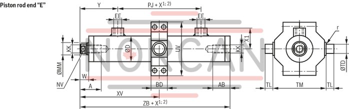
| 1) | X = stroke length |
| 2) | Observe the minimum stroke length “Xmin.“ |
Piston Ø (ØAL) 40 … 200 mm
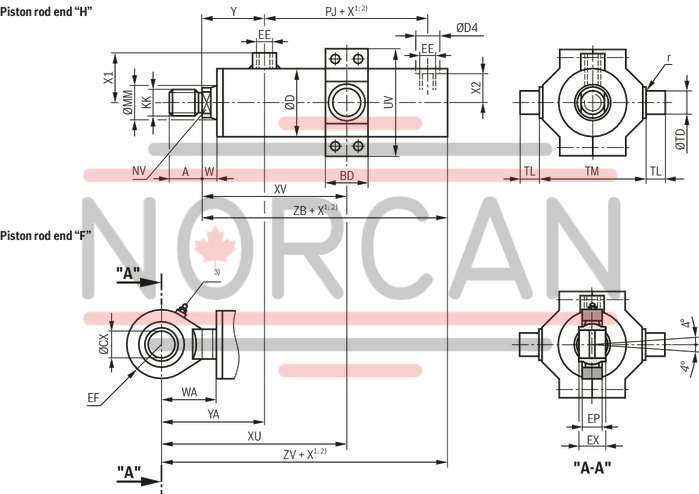
| 1) | X = stroke length |
| 2) | Observe the minimum stroke length “Xmin.“ |
| 3) | Lubricating nipple, cone head form A according to DIN 71412 |
Dimensions: type of mounting MT4 (for operating pressure up to 160 bar)
|
ØAL |
ØMM at nominal pressure 160 bar |
KK |
A |
AB |
NV |
W |
WA |
ØD |
Y |
YA |
PJ |
X min. |
XV 1) min. 1) |
XV max. |
XU 1) min. 1) |
XU 1) max. 1) |
EE |
ØD4 |
X1 |
X2 |
ZB |
ZV |
BD |
UV max. |
TD |
TL |
TM |
r |
ØCX |
EX |
EP max. |
EF |
|||||||
|
mm |
mm |
mm |
mm |
mm |
mm |
mm |
mm |
mm |
mm |
mm |
mm |
mm |
mm |
mm |
mm |
mm |
mm |
mm |
mm |
mm |
mm |
mm |
mm |
mm |
mm |
mm |
mm |
mm |
mm |
mm |
|||||||||
| 25 | 14 mm / - | M10 | 26 | 21 | 12 | 10 | - | 32 | 44 | - | 26 | 21 | 68 | 47 + X | - | - | G1/8 | - | 245 | ± 1 | - | - | 104 | - | 20 | 66 | 12 |
f8 |
10 | 63 |
h12 |
1 | - |
- - |
- |
- - |
- | - | - |
| 32 | 18 mm / - | M12 | 28 | 25 | 15 | 11 | - | 40 | 48 | - | 31 | 28 | 78 | 50 + X | - | - | G1/4 | - | 33 | ± 1 | - | - | 116 | - | 25 | 77 | 16 |
f8 |
12 | 75 |
h12 |
1 | - |
- - |
- |
- - |
- | - | - |
| 40 | 22 mm / - | M16 x 1.5 | 22 | - | 17 | 13 | 44 | 50 | 60 | 91 | 50 | 23 | 94 | 71 + X | 125 | 102 + X | G1/4 | 23 | 39 | ± 1 | 22 | ± 1 | 124 | 155 | 35 | 88 | 20 |
f8 |
16 | 90 |
h12 |
15 | 20 |
H7 |
20 |
h12 |
16 | 28 | ± 2 |
| 50 | 28 mm / - | M20 x 1.5 | 28 | - | 22 | 13 | 50 | 60 | 62 | 99 | 57 | 32 | 104 | 72 + X | 141 | 109 + X | G3/8 | 27 | 45 | ± 1 | 27 | ± 1 | 135 | 172 | 40 | 102 | 25 |
f8 |
20 | 105 |
h12 |
15 | 25 |
H7 |
25 |
h12 |
20 | 33 | ± 2 |
| 63 | 36 mm / - | M27 x 2 | 36 | - | 28 | 14 | 63 | 75 | 68 | 117 | 71 | 37 | 119 | 82 + X | 168 | 131 + X | G1/2 | 36 | 55 | ± 1 | 335 | ± 1 | 159 | 208 | 50 | 129 | 32 |
f8 |
25 | 120 |
h12 |
2 | 32 |
H7 |
32 |
h12 |
22 | 42 | ± 2 |
| 80 | 45 mm / - | M33 x 2 | 45 | - | 36 | 16 | 76 | 95 | 84 | 144 | 80 | 51 | 144 | 93 + X | 204 | 153 + X | G1/2 | 36 | 65 | ± 1 | 445 | ± 1 | 185 | 245 | 65 | 148 | 40 |
f8 |
32 | 135 |
h12 |
25 | 40 |
H7 |
40 |
h12 |
26 | 51 | ± 2 |
| 100 | 56 mm / - | M42 x 2 | 56 | - | 46 | 18 | 88 | 120 | 90 | 160 | 89 | 69 | 162 | 93 + X | 232 | 163 + X | G3/4 | 43 | 80 | ± 1 | 57 | ± 1 | 202 | 272 | 80 | 178 | 50 |
f8 |
40 | 160 |
h12 |
25 | 50 |
H7 |
50 |
h12 |
34 | 61 | ± 2 |
| 125 | 70 mm / - | M48 x 2 | 63 | - | 60 | 20 | 106 | 150 | 99 | 185 | 97 | 85 | 183 | 98 + X | 269 | 184 + X | G3/4 | 43 | 95 | ± 1 | 72 | ± 1 | 221 | 307 | 100 | 218 | 63 |
f8 |
50 | 195 |
h12 |
3 | 63 |
H7 |
63 |
h12 |
42 | 76 | ± 2 |
| 1) | Trunnion position freely selectable. When ordering, always specify the “XV / XU” dimensions in the plain text in mm. |
Dimensions: Type of mounting MT4 (for operating pressure up to 250 bar)
|
ØAL |
ØMM at nominal pressure 250 bar |
KK |
A |
AB |
NV |
W |
WA |
ØD |
Y |
YA |
PJ |
X min. |
XV 1) min. 1) |
XV max. |
XU 1) min. 1) |
XU 1) max. 1) |
EE |
ØD4 |
X1 |
X2 |
ZB |
ZV |
BD |
UV max. |
TD |
TL |
TM |
r |
ØCX |
EX |
EP max. |
EF |
|||||||
|
mm |
mm |
mm |
mm |
mm |
mm |
mm |
mm |
mm |
mm |
mm |
mm |
mm |
mm |
mm |
mm |
mm |
mm |
mm |
mm |
mm |
mm |
mm |
mm |
mm |
mm |
mm |
mm |
mm |
mm |
||||||||||
| 40 | 25 mm / - | M20 x 1.5 | 28 | - | 19 | 15 | 41 | 52 | 62 | 88 | 53 | 60 | 112 | 52 + X | 138 | 78 + X | G1/4 | 23 | 46 | ± 1 | 23 | ± 1 | 129 | 155 | 40 | 98 | 25 |
f8 |
20 | 95 |
h12 |
15 | 25 |
H7 |
25 |
h12 |
20 | 33 | ± 2 |
| 50 | 32 mm / - | M27 x 2 | 36 | - | 27 | 15 | 52 | 62 | 64 | 101 | 62 | 66 | 121 | 55 + X | 158 | 92 + X | G3/8 | 27 | 52 | ± 1 | 28 | ± 1 | 141 | 178 | 50 | 114 | 32 |
f8 |
25 | 112 |
h12 |
15 | 32 |
H7 |
32 |
h12 |
22 | 42 | ± 2 |
| 63 | 40 mm / - | M33 x 2 | 45 | - | 32 | 17 | 64 | 78 | 71 | 118 | 71 | 78 | 135 | 57 + X | 182 | 104 + X | G1/2 | 36 | 65 | ± 1 | 35 | ± 1 | 162 | 209 | 60 | 137 | 40 |
f8 |
32 | 125 |
h12 |
15 | 40 |
H7 |
40 |
h12 |
26 | 51 | ± 2 |
| 80 | 50 mm / - | M42 x 2 | 56 | - | 41 | 19 | 74 | 100 | 84 | 139 | 78 | 91 | 157 | 66 + X | 212 | 121 + X | G1/2 | 36 | 76 | ± 1 | 47 | ± 1 | 182 | 237 | 75 | 167 | 50 |
f8 |
40 | 150 |
h12 |
2 | 50 |
H7 |
50 |
h12 |
34 | 61 | ± 2 |
| 100 | 63 mm / - | M48 x 2 | 63 | - | 50 | 19 | 90 | 125 | 91 | 162 | 90 | 115 | 180 | 65 + X | 251 | 136 + X | G3/4 | 43 | 91 | ± 1 | 60 | ± 1 | 204 | 275 | 100 | 201 | 63 |
f8 |
50 | 180 |
h12 |
25 | 63 |
H7 |
63 |
h12 |
42 | 76 | ± 2 |
| 125 | 80 mm / - | M64 x 3 | 85 | - | 65 | 22 | 112 | 160 | 105 | 195 | 102 | 135 | 208 | 73 + X | 298 | 163 + X | G3/4 | 43 | 109 | ± 1 | 77 | ± 1 | 230 | 320 | 120 | 257 | 80 |
f8 |
63 | 224 |
h12 |
25 | 80 |
H7 |
80 |
h12 |
52 | 92 | ± 2 |
| 1) | Trunnion position freely selectable. When ordering, always specify the “XV / XU” dimensions in the plain text in mm. |
Type of mounting M00: no mounting
Piston Ø (ØAL) 25 … 32 mm
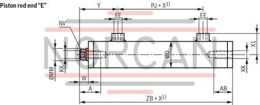
| 1) | X = stroke length |
Dimensions: Type of mounting M00
|
ØAL |
ØMM at nominal pressure 160 bar |
KK |
A |
AB |
NV |
W |
ØD |
Y |
PJ |
EE |
X1 |
ZB |
|
|
mm |
mm |
mm |
mm |
mm |
mm |
mm |
mm |
mm |
mm |
mm |
|||
| 25 | 14 mm / - | M10 | 26 | 21 | 12 | 10 | 32 | 44 | 26 | G1/8 | 24.5 | ± 1 | 104 |
| 32 | 18 mm / - | M12 | 28 | 25 | 15 | 11 | 40 | 48 | 31 | G1/4 | 33 | ± 1 | 116 |
Kinking
For the admissible stroke length with flexibly guided load and a factor of 3.5 for safety against kinking, please refer to the relevant table. For other installation positions of the cylinder, the admissible stroke length must be interpolated.
Admissible stroke length for non-guided load on request.
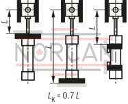
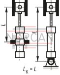
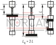
Kinking calculations are carried out according to the following formulas:
1. Calculation according to Euler

if λ > λg
2. Calculation according to Tetmajer

if λ ≤ λg
Explanation
|
E |
= |
module of elasticity in N/mm2 |
|
|
= |
2.1 x 10⁵ for steel |
||
|
l |
= |
Geometrical moment of inertia in mm4 |
|
|
for circular cross-section |

|
||
|
v |
= |
3.5 (safety factor) |
|
|
LK |
= |
free kinking length in mm (dependent on type of mounting; see sketches A, B, C) |
|
|
d |
= |
Piston rod Ø in mm |
|
|
λ |
= |
Slenderness ratio |
|
|
= |

|

|
|
|
Re |
= |
Yield strength of the piston rod material |
|
Influence of the type of mounting on the kinking length:
|
|
|
Admissible stroke length
Type of mounting MP5
|
ØAL |
ØMM |
admissible stroke length with |
||||||||
|
80 bar |
160 bar |
250 bar |
||||||||
|
0° |
45° |
90° |
0° |
45° |
90° |
0° |
45° |
90° |
||
|
mm |
mm |
mm |
mm |
mm |
mm |
mm |
mm |
mm |
mm |
|
| 25 | 14 mm / - | 170 | 175 | 185 | 105 | 105 | 110 | - | - | - |
| 32 | 18 mm / - | 230 | 230 | 250 | 145 | 145 | 150 | - | - | - |
| 40 | 22 mm / - | 285 | 290 | 315 | 185 | 190 | 195 | - | - | - |
| 25 mm / - | 370 | 380 | 425 | 255 | 260 | 270 | 190 | 190 | 195 | |
| 50 | 28 mm / - | 380 | 390 | 420 | 255 | 260 | 265 | - | - | - |
| 32 mm / - | 490 | 505 | 570 | 345 | 350 | 365 | 260 | 265 | 270 | |
| 63 | 36 mm / - | 500 | 515 | 565 | 345 | 350 | 360 | - | - | - |
| 40 mm / - | 600 | 625 | 715 | 435 | 440 | 465 | 330 | 335 | 340 | |
| 80 | 45 mm / - | 610 | 630 | 705 | 430 | 440 | 455 | - | - | - |
| 50 mm / - | 725 | 755 | 890 | 535 | 545 | 580 | 410 | 415 | 430 | |
| 100 | 56 mm / - | 755 | 780 | 890 | 545 | 555 | 580 | - | - | - |
| 63 mm / - | 910 | 950 | 1145 | 685 | 700 | 755 | 540 | 545 | 565 | |
| 125 | 70 mm / - | 935 | 975 | 1125 | 690 | 705 | 740 | - | - | - |
| 80 mm / - | 1125 | 1180 | 1485 | 870 | 895 | 985 | 695 | 705 | 740 | |
| 160 | 100 mm / - | 1350 | 1420 | 1810 | 1050 | 1085 | 1200 | 840 | 855 | 900 |
| 200 | 125 mm / - | 1645 | 1735 | 2250 | 1300 | 1340 | 1500 | 1045 | 1065 | 1130 |
Installation position
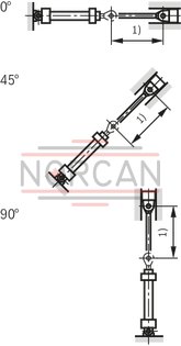
| 1) | Adm. stroke length |
Admissible stroke length
Type of mounting MF3
|
ØAL |
ØMM |
admissible stroke length with |
||||||||
|
80 bar |
160 bar |
250 bar |
||||||||
|
0° |
45° |
90° |
0° |
45° |
90° |
0° |
45° |
90° |
||
|
mm |
mm |
mm |
mm |
mm |
mm |
mm |
mm |
mm |
mm |
|
| 25 | 14 mm / - | 600 | 600 | 600 | 485 | 485 | 495 | - | - | - |
| 32 | 18 mm / - | 800 | 800 | 800 | 630 | 635 | 645 | - | - | - |
| 40 | 22 mm / - | 1000 | 1000 | 1000 | 735 | 740 | 755 | - | - | - |
| 25 mm / - | 1000 | 1000 | 1000 | 935 | 950 | 985 | 755 | 760 | 770 | |
| 50 | 28 mm / - | 1200 | 1200 | 1200 | 955 | 965 | 990 | - | - | - |
| 32 mm / - | 1200 | 1200 | 1200 | 1200 | 1200 | 1200 | 990 | 1000 | 1025 | |
| 63 | 36 mm / - | 1400 | 1400 | 1400 | 1250 | 1260 | 1310 | - | - | - |
| 40 mm / - | 1400 | 1400 | 1400 | 1400 | 1400 | 1400 | 1230 | 1240 | 1275 | |
| 80 | 45 mm / - | 1700 | 1700 | 1700 | 1530 | 1550 | 1620 | - | - | - |
| 50 mm / - | 1700 | 1700 | 1700 | 1700 | 1700 | 1700 | 1505 | 1520 | 1570 | |
| 100 | 56 mm / - | 2000 | 2000 | 2000 | 1875 | 1910 | 2000 | - | - | - |
| 63 mm / - | 2000 | 2000 | 2000 | 2000 | 2000 | 2000 | 1910 | 1935 | 2000 | |
| 125 | 70 mm / - | 2300 | 2300 | 2300 | 2300 | 2300 | 2300 | - | - | - |
| 80 mm / - | 2300 | 2300 | 2300 | 2300 | 2300 | 2300 | 2300 | 2300 | 2300 | |
Installation position

| 1) | Adm. stroke length |
Admissible stroke length
Type of mounting MT4 (trunnion position in cylinder center)
|
ØAL |
ØMM |
admissible stroke length with |
||||||||
|
80 bar |
160 bar |
250 bar |
||||||||
|
0° |
45° |
90° |
0° |
45° |
90° |
0° |
45° |
90° |
||
|
mm |
mm |
mm |
mm |
mm |
mm |
mm |
mm |
mm |
mm |
|
| 25 | 14 mm / - | 270 | 275 | 290 | 180 | 180 | 185 | - | - | - |
| 32 | 18 mm / - | 355 | 360 | 385 | 245 | 245 | 250 | - | - | - |
| 40 | 22 mm / - | 410 | 420 | 450 | 280 | 285 | 290 | - | - | - |
| 25 mm / - | 515 | 530 | 590 | 365 | 370 | 380 | 275 | 275 | 280 | |
| 50 | 28 mm / - | 540 | 555 | 595 | 375 | 380 | 390 | - | - | - |
| 32 mm / - | 680 | 705 | 790 | 495 | 500 | 520 | 380 | 380 | 390 | |
| 63 | 36 mm / - | 710 | 730 | 800 | 505 | 510 | 525 | - | - | - |
| 40 mm / - | 840 | 870 | 995 | 620 | 630 | 660 | 480 | 485 | 495 | |
| 80 | 45 mm / - | 860 | 885 | 985 | 620 | 625 | 650 | - | - | - |
| 50 mm / - | 1010 | 1055 | 1225 | 755 | 770 | 815 | 595 | 600 | 615 | |
| 100 | 56 mm / - | 1050 | 1090 | 1230 | 770 | 780 | 815 | - | - | - |
| 63 mm / - | 1265 | 1320 | 1580 | 965 | 990 | 1055 | 770 | 780 | 800 | |
| 125 | 70 mm / - | 1300 | 1350 | 1555 | 970 | 990 | 1040 | - | - | - |
| 80 mm / - | 1565 | 1645 | 2050 | 1230 | 1260 | 1380 | 995 | 1010 | 1050 | |
Installation position

| 1) | Adm. stroke length |
|
ØAL |
= |
Piston Ø |
|
ØMM |
= |
Piston rod Ø |
Swivel head
CGKD

Swivel head
CGKD
Data sheet
Configurator / CAD
Swivel head
CGKL
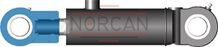
Swivel head
CGKL
Data sheet
Configurator / CAD
Clevis bracket
CLCA

Clevis bracket
CLCA
Data sheet
Configurator / CAD
Clevis bracket
CLCD

Clevis bracket
CLCD
Data sheet
Configurator / CAD
Trunnion bearing block
CLTB

Trunnion bearing block
CLTB
Data sheet
Configurator / CAD