


BOSCH REXROTH
R900248931
- BOSCH REXROTH
- Material:R900248931
- Model:4WSE2EM6-2X/10B8ET315K17EV
Quantity in stock: 0
The Bosch Rexroth 4WSE2EM6-2X/10B8ET315K17EV (R900248931) is a high-performance servo valve designed for precise control of position, force, pressure, or velocity. This valve is distinguished by its stage directional capabilities and adherence to the ISO porting pattern standard, ensuring compatibility with a wide range of systems. The valve's operation is based on an electromechanical converter torque motor that works in conjunction with a hydraulic amplifier, which operates on the nozzle-flapper plate principle, and a control spool within a sleeve. The torque motor responds to electrical input signals by generating force through a permanent magnet acting on an armature. This interaction results in torque that moves the flapper plate and creates a pressure differential across the control spool. As the spool adjusts its position, it regulates the connection between the pressure port and actuator ports, controlling flow accordingly. Mechanical feedback is provided via a bending spring that balances the electromagnetic torque with the feedback torque until equilibrium is achieved. The servo valve's flow is proportional to the electrical signal received but also depends on the valve's pressure drop. This specific model comes equipped with integrated special control electronics (OBE), which are fine-tuned for this type of valve and housed within the connector in the cover cap of the torque motor. These electronics amplify analog input signals to precisely actuate the servo valve in a flow-controlled manner. Key specifications include suitability for subplate mounting with gap-sealed pressure chambers at the control sleeve to prevent wear of seal rings, as well as an accessible filter for maintenance. The unit boasts dry control motor technology that prevents contamination of solenoid gaps by hydraulic fluid and can operate as both 3-way and 4-way versions due to its versatile design. With a maximum operating pressure of 315 bar and maximum flow rate of 10 liters per minute, this Bosch Rexroth servo valve ensures reliable performance for demanding applications.
4WS(E)2EM 6-2X/…
Valves of this type are electrically operated, 2-stage directional servo valves with porting pattern according to ISO 4401-03-02-0-05. They are mainly used to control position, force, pressure or velocity.
These valves are made of an electro-mechanical converter (torque motor) (1), a hydraulic amplifier (principle: nozzle flapper plate) (2) and a control spool (3) in a sleeve (2nd stage) which is connected with the torque motor via a mechanical feedback.
An electrical input signal at the coils (4) of the torque motor generates a force by means of a permanent magnet which acts on the armature (5), and in connection with a torque tube (6) results in a torque. This causes the flapper plate (7) which is connected to the torque tube (6) via a bolt to move from the central position between the two control nozzles (8), and a pressure differential is created across the front sides of the control spool (3). The pressure differential results in the spool changing its position, which results in the pressure port being connected to one actuator port and, at the same time, the other actuator port being connected to the return flow port.
The control spool is connected to the flapper plate or the torque motor by means of a bending spring (mechanical feedback) (9). The position of the spool is changed until the feedback torque across the bending spring and the electro-magnetic torque of the torque motor are balanced and the pressure differential at the nozzle flapper plate system becomes zero.
The stroke of the control spool and consequently the flow of the servo valve are controlled proportional to the electrical input signal. It must be noted that the flow depends on the valve pressure drop.
Type 4WS2EM 6-2X/… for external control electronics
External control electronics (servo amplifier) serve the actuation of the valve, amplifying an analog input signal (command value) so that with the output signal, the servo valve is actuated in a flow-controlled form.
Type 4WSE2EM 6-2X/… with OBE
For amplification of the analog input signal, special control electronics (10) adjusted to this valve type have been integrated. They are attached to the connector (11) in the cover cap of the torque motor.

|
01 |
02 |
03 |
04 |
05 |
06 |
07 |
08 |
09 |
10 |
11 |
|||
|
6 |
- |
2X |
/ |
B |
ET |
K17 |
V |
* |
|
01 |
Electrically operated 2-stage servo valve in 4-way version with mechanical feedback and external control electronics |
4WS2EM |
|
Electrically operated 2-stage servo valve in 4-way version with mechanical feedback and integrated control electronics (OBE) |
4WSE2EM |
|
|
02 |
Size 6 |
6 |
|
03 |
Component series 20 ... 29 (20 ... 29: unchanged installation and connection dimensions) - Size 6 |
2X |
|
Rated flow at 70 bar valve pressure differential |
||
|
04 |
2 l/min |
2 |
|
5 l/min |
5 |
|
|
10 l/min |
10 |
|
|
15 l/min |
15 |
|
|
20 l/min |
20 |
|
|
25 l/min |
25 |
|
|
05 |
Valves for external control electronics: Coil no. 11 (30 mA / 85 Ω per coil) |
11 |
|
Valves with integrated control electronics: |
8 |
|
|
Valves with integrated control electronics: |
9 |
|
|
06 |
Pilot oil supply internal, pilot oil return internal |
ET |
|
Inlet pressure range |
||
|
07 |
10 … 210 bar |
210 |
|
10 … 315 bar |
315 |
|
|
Electrical connection |
||
|
08 |
Without mating connector, with connector Mating connector, separate order |
K17 |
|
Control spool overlap |
||
|
09 |
0 ... 0,5 % positiv |
D |
|
0 ... 0,5% negativ |
E |
|
|
10 |
FKM seals, suitable for mineral oil (HL, HLP) according to DIN 51524 |
V |
|
11 |
Further details in the plain text |
* |
For applications outside these parameters, please consult us!
general
|
Type |
4WS(E)2EM | ||
|
Size |
6 | ||
|
Component series |
2X | ||
|
Porting pattern |
ISO 4401-03-02-0-05 | ||
|
Installation position |
any – ensure that during start-up of the system, the pilot control is supplied with sufficient pressure (≥10 bar). | ||
|
Storage temperature range |
°C |
-20 … +80 | |
|
Weight |
kg |
1.1 | |
|
Ambient temperature range |
with OBE |
°C |
-20 … +60 |
|
without OBE |
°C |
-30 … +100 | |
hydraulic
|
Type |
4WS(E)2EM | ||
|
Maximum operating pressure |
bar |
315 | |
|
Maximum operating pressure |
Port A |
bar |
315 |
|
Port B |
bar |
315 | |
|
Port P |
bar |
315 | |
|
Return flow pressure |
Port T |
bar |
Pressure peaks < 100, static < 10 |
|
Rated flows qv nom at 70 bar valve pressure differential (35 bar/control edge) 1) |
l/min |
2 | |
|
Maximum control spool stroke possible 2) |
% |
120 … 170 | |
|
Hydraulic fluid |
see table | ||
|
Hydraulic fluid temperature range |
°C |
-30 … +80 | |
|
preferably |
°C |
+40 … +50 | |
|
Maximum admissible degree of contamination of the hydraulic fluid, cleanliness class according to ISO 4406 (c) 3) |
Class 18/16/13 according to ISO 4406 (c) | ||
|
Viscosity range |
mm²/s |
15 … 380 | |
|
preferably |
mm²/s |
30 … 45 | |
|
Feedback system |
mechanical | ||
|
Hysteresis (dither-optimized) |
% |
≤ 1.5 | |
|
Range of inversion (dither-optimized) |
% |
≤ 0.2 | |
|
Response sensitivity (dither-optimized) |
% |
≤ 0.2 | |
|
Pressure amplification with 1 % control spool stroke change (from the hydraulic zero point) 4) |
% |
≥ 50 | |
|
Zero adjustment flow over the entire operating pressure range 5) |
% |
≤ 3 | |
|
Zero shift upon change of |
Hydraulic fluid temperature |
%/20° C |
≤ 1 |
|
Ambient temperature |
%/20° C |
≤ 1 | |
|
Operating pressure 80 … 120 % of pP |
%/100 bar |
≤ 2 | |
|
Return flow pressure 0 … 10 % of pP |
%/bar |
≤ 1 | |
| 1) | Tolerance ±10 % with valve pressure differential Δp = 70 bar |
| 2) | With mechanical end position (in an error case) related to nominal stroke |
| 3) | The cleanliness classes specified for the components must be adhered to in hydraulic systems. Effective filtration prevents faults and simultaneously increases the life cycle of the components. For the selection of the filters, see www.boschrexroth.com/filter. |
| 4) | of pp from the hydraulic zero point |
| 5) | long-term ≤ 5% |
|
Zero flow (with spool overlap "E", measured without dither signal) |
l/min |

|
|
Hydraulic fluid |
Classification |
Suitable sealing materials |
Standards |
|
Mineral oils and related hydrocarbons |
HL, HLP |
NBR / FKM |
DIN 51524 |
|
For more information and data on the use of other hydraulic fluids please contact us. |
|||
electrical
|
Type |
4WS(E)2EM | ||
|
Size |
6 | ||
|
Protection class according to EN 60529 |
IP65 (with mating connector mounted and locked) | ||
|
Type of signal |
analog | ||
|
Inductivity 1) |
Serial connection |
H |
1 |
|
Parallel connection |
H |
0.25 | |
| 1) | With 60 Hz and 100% rated current |
(measured with HLP32, ϑOil =40 ±5 °C)
Flow/load function with maximum valve opening (tolerance ±10 %)

Tolerance field of the flow/signal function with constant valve pressure differential Δp

Transition function with pressure rating 315 bar

Frequency response with pp = 315 bar - measured with pressure rating 315 barbar

Dependency of the frequency f at -90° of the operating pressure and the inlet amplitude

(measured with HLP46, ϑOil = 40 ±5 °C)
Type 4WSE2EM 6...

Type 4WS2EM 6...

Type 4WS2EM 6...

The coils are connected in parallel in the mating connector or to the amplifier (see figure). For serial connection, contacts B and C have to be connected. The bridge E-F can be used for electrical recognition of the correct connection of the connector or for cable break detection.
Electrical control from A (+) to D (-) provides for the direction of flow P → A and B → T. Reverse electrical control provides for direction of flow P → B and A → T.
Type 4WSE2EM 6...

|
Pin assignment |
Contact |
Current control "13" |
Voltage control "9" |
|
Supply voltage (tolerance ±3 %, residual ripple <1 %) Current consumption |
A |
+ 15 V, max. 150 mA |
+ 15 V, max. 150 mA |
|
B |
- 15 V, max. 150 mA |
- 15 V, max. 150 mA |
|
|
C |
⊥ |
⊥ |
|
|
Command value |
D |
±10 mA; Re = 1 kΩ |
± 10 V; Re ≥ 8 kΩ, Ie = 1,2 mA |
|
Command value reference |
E |
||
|
F |
not assigned |
||
Command value:
Command value at the mating connector port D = positive against mating connector port E results in flow from P to A and B to T.
Command value at the mating connector port D = negative against mating connector port E results in flow from P to B and A to T.
Notice:
Electrical signals provided via control electronics (e.g. actual value) must not be used to switch off safety-relevant machine functions!
Connection line:
4- and/or 6-wire, 0.75 mm², shielded, with litz wires according to DIN VDE 0812 (e.g. line type LIYCY 4 and/or 6 x 0.75 mm²)
Dimensions in mm

|
1 |
Space required to remove the mating connector |
|
2 |
Cap |
|
3 |
Valve mounting screws (included in the scope of delivery): |
|
4 |
Identical seal rings for ports A, B, P, and T |
|
5 |
Name plate |
|
6.1 |
Mating connector, separate order |
|
6.2 |
Mating connector, separate order |
|
7 |
Connection line |
|
8 |
Filter |
|
9 |
Plug screw (SW6), after filter exchange, tighten it applying a tightening torque MA = 30 Nm |
|
10 |
Dimensions in brackets for valve with integrated control electronics (OBE) |
|
11 |
Machined valve contact surface; Porting pattern according to ISO 4401-03-02-0-05 |
|
Subplates must be ordered separately |
|
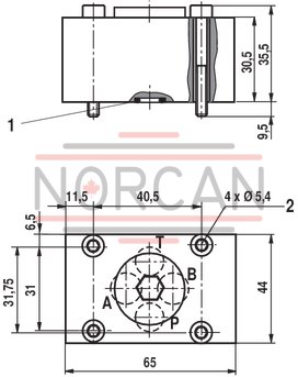
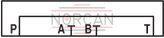
Dimensions in mm
Dimensions in mm
|
1 |
R-ring 9.81 x 1.5 x 1.78 (ports P, A, B, T) |
|
2 |
Mounting screws (included in the scope of delivery):4 hexagon socket head cap screws ISO 4762 - M5 x 40- 10.9-flZn-240h-L, MA = 7 Nm ± 10 % |
To ensure proper operation of the servo valves, it is necessary to flush the system before commissioning.
The following values are guidelines for the flushing time per system: t ≥ V : QV x 5
t = flushing time in h
V = tank capacity in l
QV = Pump flow in l/min
When replenishing more than 10% of the tank capacity, the flushing procedure must be repeated.
The use of a directional valve with port according to ISO 4401-03-02-0-05 is suited better than a flushing plate. With this valve, you can also flush the actuator ports.