

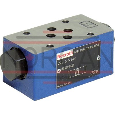
BOSCH REXROTH
R900347505
$387.33 USD
- BOSCH REXROTH
- Material:R900347505
- Model:Z2S6-2-6X/V
Quantity in stock: 6
The Bosch Rexroth Z2S6-2-6X/V (R900347505) is a mechanically actuated industrial hydraulic valve designed for high-performance applications. It features reliable blocking of oil flow in accordance with its seat valve design and is directly actuated. The model has a spool symbol of A A, B B, indicating that it allows free flow from A to A or B to B, while blocking the flow in the opposite direction. This capability makes it suitable for applications requiring leakage-free blocking of actuator ports, even during extended periods of non-operation. With a maximum pressure capacity and a specified number of ports, this valve is equipped for robust use. The type of actuation is mechanical, ensuring precise control over the hydraulic system it is integrated into. It comes in a specific size and can handle a maximum flow rate as indicated by its specifications. The Z2S6-2-6X/V offers various connection options including sandwich plate mounting and adheres to both NFPA and ISO connection diagram standards. In terms of construction, it features preopening which serves to dampen decompression shocks, thus protecting against potential switching shocks that could cause wear or noise issues in the hydraulic system. This two-stage setup with increased control open ratio allows for secure unloading even at low pilot pressures. The valve accommodates multiple types of hydraulic fluids including HL, HLP, HLPD, HVLP, HVLPD, HETG, HEES, HEPG, HFDU, and HFDR with FKM seals ensuring compatibility and resilience across different operating environments. Additionally, its weight is noted alongside the number of switching positions available. This model also includes options for various cracking pressures and preopening features upon request. Special versions can be made available as per custom requirements. The Z2S6-2-6X/V valve exemplifies Bosch Rexroth's commitment to providing reliable components for sophisticated hydraulic systems.
Size 6, A1 → A2, B1 → B2, mechanically actuated
Industrial hydraulic valve in a high performance range. Reliable blocking of the oil flow according to the hydraulic symbol
Unpacked Weight: 0.96 kg
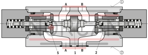
The isolator valve type Z2S is a releasable check valve in sandwich plate design.
It is used for the leakage-free blocking of one or two actuator ports, also in case of longer standstill times.
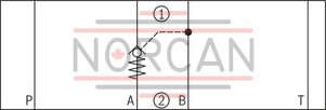
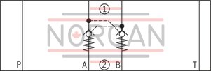
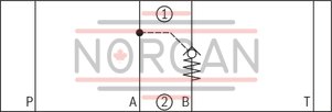
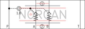
In direction A① to A② or B① to B②, there is a free flow; in the opposite direction, the flow is blocked.
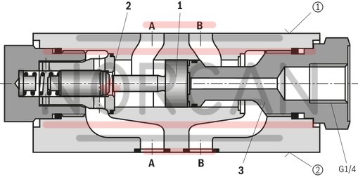
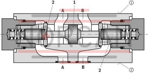
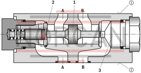
If, for example, there is a flow through the valve in direction A① to A②, the control spool (1) is moved in the direction of the B side, opens the ball seat valve (2) and then pushes the poppet (3) off its seat. Hydraulic fluid can now flow from B➁ to B➀.
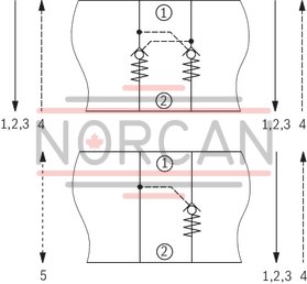
In order to allow the ball seat valve (2) to be safely closed, the control spool (1) must be hydraulically unloaded (see circuit example).
Pre-opening
Due to the pre-opening, there is a damped decompression of the pressurized liquid. Thus, possible switching shocks are avoided. The two-stage set-up with an increased control open ratio means even low pilot pressure can be unloaded securely.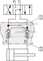
Notice:
In valves without pre-opening, sudden unloading of pent-up pressure volume may occur. Resulting switching shocks may lead to premature wear on installed components, as well as noise formation.
|
1 |
Control spool, area A2 |
|
2 |
Poppet, area A1 |
|
3 |
Stop |
Type Z2S 6 A…SO40
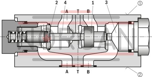
Type Z2S 6 A…SO60
|
1 |
Control spool, area A2 |
|
2 |
Poppet, area A1 |
|
3 |
Stop |
|
4 |
Control spool, area A4 |
|
5 |
Pre-opening, area A3 |
Type Z2S 6 -…SO55 (with pre-opening)
| Seat valve |
| Direct actuated |
| Cracking pressure 3 bar |
| Leakage-free blocking in channel A and B |
| Component series 6X |
| Size 6 |
| Maximum operating pressure 350 bar |
| Maximum flow 80 l/min |
| Data Sheet | Download Data Sheet |
| 3D CAD | Download 3D CAD |
| Manual | Download Manual |
| Manual | Download Manual |
| Manual | Download Manual |
| Manual | Download Manual |
| Manual | Download Manual |
| Spool symbol | A1 → A2, B1 → B2 |
| Max. pressure | 350 |
| Productgroup ID | 9,10,11,12,13,14 |
| Number of ports | 4 |
| Type of actuation | with mechanical actuation |
| Size | 6 |
| Max. flow | 80 |
| Type of connection | Sandwich plate |
| Connection diagram NFPA | NFPA T3.5.1 R2-2002 D03 |
| Size_CETOP | D03 |
| Connection diagram | ISO 4401-03-02-0-05 |
| Number of switching positions | 2 |
| Weight | 0.96 |
| Seals | FKM |
| Hydraulic fluid | HL,HLP,HLPD,HVLP,HVLPD,HETG,HEES,HEPG,HFDU,HFDR |
1) Corrosion-resistant surface on request: e.g."J50" thick film passivated (DIN 50979 Fe//Zn8//Cn//T0)
2) Locking pin ISO 8752-3x8-St, material no. R900005694 (separate order)
|
01 |
02 |
03 |
04 |
05 |
06 |
07 |
08 |
09 |
10 |
||
|
Z2S |
6 |
– |
6X |
/ |
* |
|
01 |
Check valve, Sandwich plate design |
Z2S |
|
02 |
Size 6 |
6 |
|
Leakage-free blocking |
||
|
03 |
In channel A and B |
– |
|
In channel A |
A |
|
|
In channel B |
B |
|
|
Cracking pressure |
||
|
04 |
1,5 bar |
1 |
|
3 bar |
2 |
|
|
6 bar |
3 |
|
|
05 |
Component series 60 … 69 (60 … 69: unchanged installation and connection dimensions) |
6X |
|
06 |
Surface without corrosion resistance 1) |
no code |
|
Seal material |
||
|
07 |
NBR seals |
no code |
|
FKM seals |
V |
|
|
The selection is dependent on the operating parameters (hydraulic fluid, temperature, etc.)! |
||
|
Locating hole |
||
|
08 |
no code |
|
|
With locating hole |
/60 |
|
|
With locating hole and locking pin ISO 8752-3x8-St 2) |
/62 |
|
|
Special version |
||
|
09 |
Without special version |
no code |
|
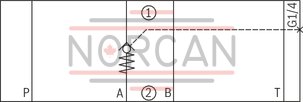
Control open by external port G1/4 (only version "A" and "B") |
SO40 |
|
|
With pre-opening |
SO55 |
|
|
Control spool unloaded to port T |
SO60 |
|
|
With pre-opening and control open from channel P |
SO150 |
|
|
Symbols (examples) see "Symbols/Circuit diagrams" |
||
|
10 |
Further details in the plain text |
* |
general
|
Size |
6 | ||
|
Weight |
kg |
0.8 | |
|
Installation position |
any | ||
|
Ambient temperature range |
NBR seals |
°C |
-30 … +80 |
|
FKM seals |
°C |
-20 … +80 | |
hydraulic
|
Size |
6 | ||
|
Maximum operating pressure |
bar |
315 | |
|
Cracking pressure 1) |
bar |
1.5 / 3 / 6 | |
|
Maximum flow |
l/min |
60 | |
|
Direction of flow |
see symbols | ||
|
Hydraulic fluid |
see table | ||
|
Hydraulic fluid temperature range (NBR seals) |
°C |
-30 … +80 | |
|
Hydraulic fluid temperature range (FKM seals) |
°C |
-20 … +80 | |
|
Viscosity range |
mm²/s |
2.8 … 500 | |
|
Maximum admissible degree of contamination of the hydraulic fluid 2) |
Class 20/18/15 according to ISO 4406 (c) | ||
|
Area ratio |
Without pre-opening |
A1/A2 ~ 1/3.5 (see sectional drawing) | |
|
With pre-opening |
A3/A2 ~ 1/12.5 (see sectional drawing) | ||
|
Version "SO60" |
A1/A4 ~ 1/7 (see sectional drawing) | ||
| 1) | in free direction |
| 2) | The cleanliness classes specified for the components must be adhered to in hydraulic systems. Effective filtration prevents faults and simultaneously increases the life cycle of the components. For the selection of the filters, see www.boschrexroth.com/filter. |
Selection of optimal sealing material also depends on the type of hydraulic fluid used.
For applications outside these parameters, please consult us!
|
Hydraulic fluid |
Classification |
Suitable sealing materials |
Standards |
|
|
Mineral oils |
HL, HLP, HLPD |
NBR, FKM |
DIN 51524 |
|
|
Bio-degradable |
Insoluble in water |
HETG |
NBR, FKM |
VDMA 24568 |
|
HEES |
FKM |
|||
|
Soluble in water |
HEPG |
FKM |
VDMA 24568 |
|
|
Flame-resistant |
Water-free |
HFDU, HFDR |
FKM |
ISO 12922 |
|
Containing water |
HFC (Fuchs Hydrotherm 46M, Petrofer Ultra Safe 620) |
NBR |
ISO 12922 |
|
Important information on hydraulic fluids!For further information and data on the use of other hydraulic fluids, please refer to data sheet 90220 or contact us! There may be limitations regarding the technical valve data (temperature, pressure range, life cycle, maintenance intervals, etc.)! The flash point of the hydraulic fluid used must be 40 K higher than the maximum solenoid surface temperature.Flame-resistant – containing water: Maximum operating pressure 210 bar Maximum hydraulic fluid temperature 60 °C Life cycle compared to operation with mineral oil HL, HLP 30 to 100 % |
||||
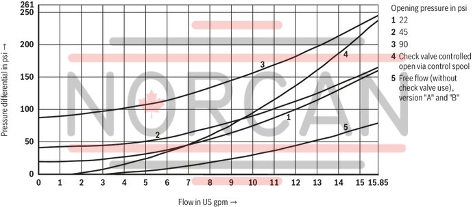
(measured with HLP46, ϑOil = 40 ±5 °C)
Δp-qV characteristic curves
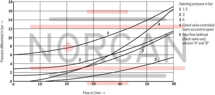
Δp-qV characteristic curves
Circuit example, schematic
|
① |
component side |
|
② |
plate side |
Type Z2S 6 A…
Type Z2S 6 -… and Z2S 6 -…SO55
Type Z2S 6 B…
Type Z2S 6 A…SO40
Type Z2S 6 A…SO60
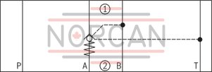
Type Z2S 6 -…SO150
|
➀ |
component side |
|
➁ |
plate side |
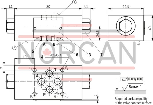
Dimensions in mm
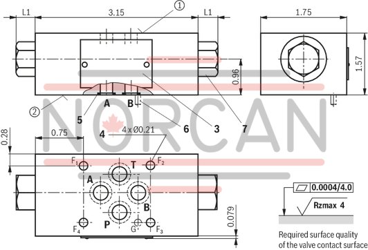
Dimensions in mm
|
Type |
L1 |
|
mm |
|
| Z2S 6...ohne Bez. | 11 |
| Z2S 6...SO40 | 11 |
| Z2S 6...SO55 |
11 1) 21.5 1) |
| Z2S 6...SO60 | 11 |
| Z2S 6...SO150 | 21.5 |
| 1) | Maximum dimension on the side of the check valve cartridge |
|
➀ |
component side – porting pattern according to DIN 24340 form A (without locating hole), or ISO 4401-03-02-0-05 (with locating hole Ø4 x 4 mm deep) and NFPA T3.5.1 R2-2002 D03 |
|
➁ |
plate side – porting pattern according to DIN 24340 form A (without locating hole), or ISO 4401-03-02-0-05 (with locating hole for locking pin ISO 8752-3x8-St; version "/60" and "/62") and NFPA T3.5.1 R2-2002 D03 |
|
3 |
Name plate |
|
4 |
Through hole for valve mounting |
|
5 |
Identical seal rings for ports A, B, P, and T |
|
6 |
Locking pin ISO 8752-3x8-St (only version "/62") |
|
7 |
Plug screw SW22 |
Valve mounting screws (separate order)
4 hexagon socket head cap screws ISO 4762 - M5 - 10.9
4 hexagon socket head cap screws N10-24 UNC
Notice!
The length of the valve mounting screws of the sandwich plate valve must be selected according to the components mounted under and over the isolator valve.
Depending on the application, screw type and tightening torque must be adjusted to the circumstances.
Please ask Rexroth for screws with the required length.
Type Z2S 6 -… (with pre-opening)
Type Z2S 6 A…
|
➀ |
component side |
|
➁ |
plate side |