

BOSCH REXROTH
R900348351
$5,081.92 USD
- BOSCH REXROTH
- Material:R900348351
- Model:L-DB50F2-3X/16
Quantity in stock: 0
The Bosch Rexroth L-DB50F2-3X/16 (R900348351) is a sophisticated pressure relief valve that is specifically designed for applications requiring low preload pressure and the capacity to handle high flow rates. This valve is part of the pilot-operated pressure valves of type LDB, which are recognized for their reliable performance in controlling hydraulic pressure. The construction of this valve includes a pipeline installation housing, a main spool guide to accommodate the pilot control valve, and a main spool that ensures precise operation. The functionality of the L-DB50F2-3X/16 involves the pressure in channel P acting on the main spool while also being directed to the pilot control valve through specific nozzles. When the preset pressure at the pilot control valve is exceeded, it triggers an opening, allowing pilot oil to be discharged directly into channel Y. This action causes the main spool to move against spring forces, connecting channel P with channel T whenever the pressure surpasses the set value at the pilot control valve. The model also features a version U, where an external spring solely holds the main spool closed. In circumstances where there's no load on the control channel, this version can achieve a reduced circulation pressure. Additionally, this product offers flexibility with its LDBF variant that operates similarly but comes as a cartridge valve without pipeline housing, suitable for flange connection according to DIN EN standards. It provides ease in pressure adjustments through a sleeve with hexagon and protective cap. Overall, Bosch Rexroth's L-DB50F2-3X/16 offers reliability and adaptability for various hydraulic applications where precise pressure relief is critical. The design and engineering encapsulate Bosch Rexroth's commitment to advanced fluid power solutions.
Pressure valves of type L–DB are pilot-operated pressure relief valves for a low preload pressure. They are suitable for high flows.
The valves basically consist of pipeline installation housing (1), main spool guide (2) for accepting the pilot control valve (5) and main spool (3).
Type L–DB
The pressure applied to channel P acts on the main spool (3) and is simultaneously applied to the pilot control valve (5) via nozzles (4) and (6). If the pressure in channel P exceeds the value set at the pilot control valve (5), the latter opens and the pilot oil is directly discharged into channel Y (7).
The main spool (3) moves upwards against the springs (8) and (9) and connects channel P to channel T as long as the pressure exceeds the value set at the pilot control valve.
With version “U”, the main spool (3) is only kept closed by the external spring (9). If the control channel is unloaded, a lower circulation pressure can be achieved.
Type L–DBF
In principle, the function of version “L–DBF” corresponds to the function of type L–DB. The valve is, however, designed as cartridge valve without pipeline housing (1).

|
01 |
02 |
03 |
04 |
05 |
06 |
07 |
08 |
09 |
10 |
11 |
||
|
L–DB |
2 |
– |
3X |
/ |
* |
|
01 |
Pressure relief valve |
L–DB |
|
02 |
Pipeline installation |
no code |
|
Cartridge valve (only size 50 … 200) |
F |
|
|
03 |
Size 40 |
40 |
|
Size 50 |
50 |
|
|
Size 65 |
65 |
|
|
Size 80 |
80 |
|
|
Size 100 |
100 |
|
|
Size 125 |
125 |
|
|
Size 150 |
150 |
|
|
Size 200 |
200 |
|
|
Size 250 |
250 |
|
|
Size 300 |
300 |
|
|
04 |
Flange connection according to DIN EN 1092-2 type 21 |
F |
|
Cartridge valve |
no code |
|
|
Adjustment type |
||
|
05 |
Sleeve with hexagon and protective cap |
2 |
|
06 |
Component series 30 ... 39 (30 ... 39: unchanged installation and connection dimensions) |
3X |
|
Set pressure |
||
|
07 |
Up to 16 bar |
16 |
|
Up to 25 bar (only size 80, 100 and 150) |
25 |
|
|
Pilot oil flow |
||
|
08 |
Internal pilot oil supply, external pilot oil return |
Y |
|
External pilot oil supply, external pilot oil return |
XY |
|
|
09 |
Standard version |
no code |
|
Valve for minimum cracking pressure |
U |
|
|
Seal material |
||
|
10 |
NBR seals |
no code |
|
FKM seals |
V |
|
|
Observe compatibility of seals with hydraulic fluid used. (Other seals upon request) |
||
|
11 |
Further details in the plain text |
* |
general
|
Size |
40 | 50 | 65 | 80 | 100 | 125 | 150 | 200 | 250 | 300 | ||
|
Weight |
kg |
11 | 15 | 26 | 32 | 50 | 75 | 100 | 180 | 300 | 475 | |
|
Installation position |
any | |||||||||||
|
Ambient temperature range |
NBR seals |
°C |
-30 … +80 | |||||||||
|
FKM seals |
°C |
-15 … +80 | ||||||||||
hydraulic
|
Size |
40 | 50 | 65 | 80 | 100 | 125 | 150 | 200 | 250 | 300 | ||
|
Maximum operating pressure |
Port P |
bar |
16 |
16 25 |
16 |
16 25 |
16 | |||||
|
Port X |
bar |
16 |
16 25 |
16 |
16 25 |
16 | ||||||
|
Port T |
bar |
16 |
16 25 |
16 |
16 25 |
16 | ||||||
|
Maximum counter pressure |
Port Y |
bar |
16 |
16 25 |
16 |
16 25 |
16 | |||||
|
Maximum flow |
l/min |
1000 | 1500 | 2700 | 3600 | 6000 | 7000 | 13000 | 24000 | 35000 | 50000 | |
|
Hydraulic fluid |
see table | |||||||||||
|
Hydraulic fluid temperature range |
NBR seals |
°C |
-30 … +80 | |||||||||
|
FKM seals |
°C |
-15 … +80 | ||||||||||
|
Viscosity range |
mm²/s |
10 … 800 | ||||||||||
|
Maximum admissible degree of contamination of the hydraulic fluid 1) |
Class 20/18/15 according to ISO 4406 (c) | |||||||||||
| 1) | The cleanliness classes specified for the components must be adhered to in hydraulic systems. Effective filtration prevents faults and simultaneously increases the life cycle of the components. For the selection of the filters, see www.boschrexroth.com/filter. |
|
Hydraulic fluid |
Classification |
Suitable sealing materials |
Standards |
Data sheet |
|
|
Mineral oils |
HL,HLP |
NBR, FKM |
DIN 51524 |
90220 |
|
|
Bio-degradable 2) |
Insoluble in water |
HETG |
FKM |
ISO 15380 |
90221 |
|
HEES |
FKM |
||||
|
Soluble in water |
HEPG |
FKM |
ISO 15380 |
||
|
Containing water 2) |
Water-free |
HFDU |
FKM |
ISO 12922 |
90222 |
|
Containing water |
HFC (Fuchs Hydrotherm 46M, Petrofer Ultra Safe 620) |
NBR |
ISO 12922 |
90223 |
|
|
Important information on hydraulic fluids: For further information and data on the use of other hydraulic fluids, please refer to the data sheets above or contact us! There may be limitations regarding the technical valve data (temperature, pressure range, life cycle, maintenance intervals, etc.)! The flash point of the hydraulic fluid used must be 40 K higher than the maximum valve surface temperature.Flame-resistant – containing water: Life cycle compared to operation with mineral oil HL, HLP 30 to 100 % |
|||||
For applications outside these parameters, please consult us!
Notice:
The maximum operating pressure is the sum of the set pressure and counter pressure!
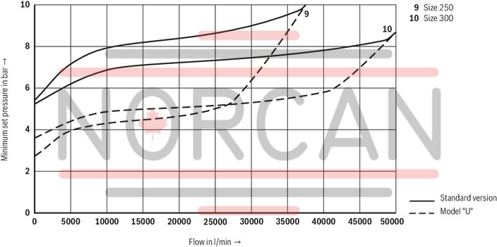
(simulated with HLP46, ϑOil = 40 °C ±5 °C)
Minimum set pressure dependent on the flow
Size 40 … 80

Minimum set pressure dependent on the flow
Size 100 … 200

Notice:
The characteristic curves were simulated with external, depressurized pilot oil return.
Minimum set pressure dependent on the flow
Size 250 and 300
Type L–DB…Y…

Type L–DB…XY…

Pipeline installation “L–DB”
Dimensions in mm

|
1 |
Name plate (position may vary depending on the size) |
|
2 |
Ports X for external pilot oil supply |
|
3 |
Ports Y for external pilot oil return |
|
4 |
Adjustment type "2" |
|
5 |
Valve mounting bores |
|
6 |
Ring bolt (2 pieces from NG50) |
|
NG |
L1 |
L2 |
L3 |
L4 |
L5 |
L6 |
H1 |
H2 |
H3 |
H4 |
B1 |
B2 |
ØD1 |
ØD3 |
ØD4 |
ØD5 |
ØD6 |
|
|
mm |
mm |
mm |
mm |
mm |
mm |
mm |
mm |
mm |
mm |
mm |
mm |
mm |
mm |
mm |
mm |
mm |
mm |
|
| 40 | 198 | ± 2 | 99 | 68 | 42.5 | 77.5 | 117 | 139 | 127 | 97.5 | - | 13 | 95 | 40 | 110 | 150 | 19 | 96 |
| 50 | 228 | ± 2 | 114 | 68 | 42.5 | 75 | 125 | 147 | 135 | 105.5 | 36 | 15 | 100 | 50 | 125 | 165 | 19 | 110 |
| 65 | 288 | ± 3 | 144 | 65 | 52 | 92 | 155 | 183 | 167 | 130 | 36 | 15 | 125 | 65 | 145 | 185 | 19 | 134 |
| 80...16 | 308 | ± 3 | 154 | 65 | 52 | 100 | 170 | 195.5 | 179.5 | 142.5 | 36 | 17 | 140 | 80 | 160 | 200 | 19 | 152 |
| 80...25 | 308 | ± 3 | 154 | 65 | 52 | 100 | 170 | 195.5 | 179.5 | 142.5 | 36 | 14 | 140 | 80 | 160 | 200 | 19 | 152 |
| 100...16 | 348 | ± 3 | 174 | 65 | 52 | 111 | 191 | 220 | 200 | 163 | 36 | 19 | 160 | 100 | 180 | 220 | 19 | 182 |
| 100...25 | 348 | ± 3 | 174 | 65 | 52 | 111 | 191 | 220 | 200 | 163 | 36 | 14 | 160 | 100 | 190 | 235 | 23 | 182 |
| 125 | 398 | ± 3 | 199 | 67 | 50.5 | 122.5 | 245 | 247.5 | 227.5 | 190.5 | 53 | 21 | - | 125 | 210 | 250 | 19 | 215 |
| 150...16 | 478 | ± 3 | 239 | 65 | 53 | 138 | 276 | 265 | 245 | 208 | 53 | 21 | - | 150 | 240 | 285 | 23 | 245 |
| 150...25 | 478 | ± 3 | 239 | 65 | 53 | 138 | 276 | 265 | 245 | 208 | 53 | 14 | - | 150 | 250 | 300 | 28 | 245 |
| 200 | 598 | ± 4 | 299 | 65 | 59 | 170 | 340 | 314 | 294 | 257 | 53 | 25 | - | 200 | 295 | 340 | 23 | 305 |
| 250 | 728 | ± 4 | 364 | 57 | 67 | 205 | 410 | 357 | 333 | 296 | 62 | 27 | - | 250 | 355 | 405 | 28 | 370 |
| 300 | 848 | ± 5 | 424 | 50 | 73.5 | 237.5 | 475 | 398 | 374 | 337 | 62 | 26 | - | 300 | 410 | 460 | 28 | 435 |
Notice:
The tightening torques stated are guidelines when using screws with the specified friction coefficients and when using a manual torque wrench (tolerance ± 10 %).
Notice:
The dimensions are nominal dimensions which are subject to tolerances.
Cartridge valve “L–DBF”
Dimensions in mm

|
1 |
Name plate (position may vary depending on the size) |
|
2 |
Ports X for external pilot oil supply |
|
3 |
Ports Y for external pilot oil return |
|
4 |
Adjustment type "2" |
|
6 |
Ring bolt (2 pieces from NG50) |
|
NG |
L3 |
L4 |
L5 |
L6 |
H4 |
H5 |
H6 |
B2 |
|
mm |
mm |
mm |
mm |
mm |
mm |
mm |
mm |
|
| 50 | 68 | 42.5 | 75 | 125 | 36 | 60.5 | 24.5 | 100 |
| 65 | 65 | 52 | 92 | 155 | 36 | 75.5 | 32 | 125 |
| 80 | 65 | 52 | 100 | 170 | 36 | 76 | 32 | 140 |
| 100 | 65 | 52 | 111 | 191 | 36 | 76 | 32 | 160 |
| 125 | 67 | 50.5 | 122.5 | 245 | 53 | 82 | 38 | - |
| 150 | 65 | 53 | 138 | 276 | 53 | 79 | 35 | - |
| 200 | 65 | 59 | 170 | 340 | 53 | 82 | 37 | - |
|
NG |
L1 |
L2 |
L3 |
L4 |
L5 |
L6 |
L7 |
ØD1 |
ØD3 |
ØD4 |
ØD5 |
ØD6 |
ØD7 |
G |
α |
β |
n |
|
mm |
mm |
mm |
mm |
mm |
mm |
mm |
mm |
mm |
mm |
mm |
mm |
mm |
° |
° |
|||
| 50 | 67.5 | 65.5 | 50 | 40.5 | 35 | 15 | 23 | 110 | 57 | 73 | 89 | 86 | 50 | M12 | 45 | 90 | 4 |
| 65 | 83.5 | 81.5 | 60 | 55.5 | 45 | 20 | 29 | 134 | 75 | 89 | 105 | 105 | 65 | M12 | 45 | 90 | 4 |
| 80 | 94.5 | 92.5 | 65 | 65.5 | 55 | 20 | 29 | 152 | 95 | 104 | 120 | 130 | 80 | M16 | 45 | 90 | 4 |
| 100 | 114.5 | 112.5 | 76 | 75.5 | 67 | 30 | 38 | 182 | 109 | 128 | 148 | 160 | 100 | M20 | 45 | 90 | 4 |
| 125 | 135 | 133 | 100 | 100.5 | 90 | 27 | 34 | 215 | 135 | 156 | 176 | 200 | 125 | M20 | 30 | 60 | 6 |
| 150 | 153.5 | 151.5 | 110 | 110.5 | 105 | 27 | 34 | 245 | 160 | 183 | 203 | 230 | 150 | M20 | 22.5 | 45 | 8 |
| 200 | 197 | 193 | 130 | 155.5 | 155 | 27 | 34 | 305 | 220 | 235 | 265 | 320 | 200 | M20 | 15 | 30 | 12 |
|
Standards: |
|
|
Workpiece edges |
DIN ISO 13715 |
|
Form and position tolerance |
DIN EN ISO 1101 |
|
General tolerances for metal-cutting procedures |
DIN ISO 2768–mK |
|
Tolerance |
DIN ISO 8015 |
|
Surface condition |
DIN EN ISO 1302 |
|
Type L–DB (not included in the scope of delivery) |
||||||
|
NG |
Quantity |
Hexagon screw 1) |
Hexagon nut |
MA in Nm 2) |
||
|
40 |
4 |
Hexagon screw ISO 4018 - M16 - 4.6 |
Hexagon nut ISO 4032-M16 |
63 |
||
|
50 |
4 |
Hexagon screw ISO 4018 - M16 - 4.6 |
Hexagon nut ISO 4032-M16 |
63 |
||
|
65 |
4 |
Hexagon screw ISO 4018 - M16 - 4.6 |
Hexagon nut ISO 4032-M16 |
63 |
||
|
80 |
8 |
Hexagon screw ISO 4018 - M16 - 4.6 |
Hexagon nut ISO 4032-M16 |
63 |
||
|
100 3) |
8 |
Hexagon screw ISO 4018 - M16 - 4.6 |
Hexagon nut ISO 4032-M16 |
63 |
||
|
100 4) |
8 |
Hexagon screw ISO 4018 - M20 - 4.6 |
Hexagon nut ISO 4032-M20 |
123 |
||
|
125 |
8 |
Hexagon screw ISO 4018 - M16 - 4.6 |
Hexagon nut ISO 4032-M16 |
63 |
||
|
150 3) |
8 |
Hexagon screw ISO 4018 - M20 - 4.6 |
Hexagon nut ISO 4032-M20 |
123 |
||
|
150 4) |
8 |
Hexagon screw ISO 4018 - M24 - 4.6 |
Hexagon nut ISO 4032-M24 |
213 |
||
|
200 |
12 |
Hexagon screw ISO 4018 - M20 - 4.6 |
Hexagon nut ISO 4032-M20 |
123 |
||
|
250 |
12 |
Hexagon screw ISO 4018 - M24 - 4.6 |
Hexagon nut ISO 4032-M24 |
213 |
||
|
300 |
12 |
Hexagon screw ISO 4018 - M24 - 4.6 |
Hexagon nut ISO 4032-M24 |
213 |
||
|
Type L–DBF (included in the scope of delivery) |
||||||
|
NG |
Fastening |
Assembly aid (from NG80) 5) |
||||
|
Quantity |
Hexagon socket head cap screw |
Part number |
MA in Nm |
Hexagon socket head cap screw |
Part number |
|
|
40 |
4 |
ISO 4762 - M12 x 70 - 10.9-flZn-240h-L |
R913000515 |
35 |
||
|
50 |
4 |
ISO 4762 - M12 x 70 - 10.9-flZn-240h-L |
R913000515 |
35 |
||
|
65 |
4 |
ISO 4762 - M16 x 90 - 10.9-flZn-240h-L |
R913000544 |
85 |
||
|
80 |
4 |
ISO 4762 - M16 x 90 - 10.9-flZn-240h-L |
R913000544 |
85 |
ISO 4762 - M16 x 120 - 8.8 |
R916445155 |
|
100 |
4 |
ISO 4762 - M20 x 100 - 10.9-flZn-240h-L |
R913000386 |
165 |
ISO 4762 - M20 x 140 - 8.8 |
R916445188 |
|
125 |
6 |
ISO 4762 - M20 x 100 - 10.9-flZn-240h-L |
R913000386 |
165 |
ISO 4762 - M20 x 160 - 8.8 |
R916445189 |
|
150 |
8 |
ISO 4762 - M20 x 100 - 10.9-flZn-240h-L |
R913000386 |
165 |
ISO 4762 - M20 x 160 - 8.8 |
R916445189 |
|
200 |
12 |
ISO 4762 - M20 x 100 - 10.9-flZn-240h-L |
R913000386 |
165 |
ISO 4762 - M20 x 140 - 8.8 |
R916445188 |
|
250 |
12 |
ISO 4762 - M24 x 100 - 10.9-flZn-240h-L |
R913000407 |
285 |
ISO 4762 - M24 x 190 - 8.8 |
R916309987 |
|
300 |
14 |
ISO 4762 - M24 x 100 - 10.9-flZn-240h-L |
R913000407 |
285 |
ISO 4762 - M24 x 220 - 8.8 |
R916445211 |
| 1) In the selection and design, DIN EN 1092-2 is to be observed | |
| 2) Tightening torques have been calculated with hexagon socket head cap screws ISO 4762 (galvanized) | |
| friction coefficient μtotal = 0.09 to 0.14 | |
| 3) Version “16” | |
| 4) Version “25” | |
| 5) In each case 2x |
Notice:
The tightening torques stated are guidelines when using screws with the specified friction coefficients and when using a manual torque wrench (tolerance ± 10 %).
Notice:
The dimensions are nominal dimensions which are subject to tolerances.
Installation bore
Dimensions in mm
Dimensions in mm
