

BOSCH REXROTH
R900409469
- BOSCH REXROTH
- Material:R900409469
- Model:DR 20 K6-1X/100YMV
Due to extremely high demand, please call 877-366-7226 for availability
The Bosch Rexroth DR 20 K6-1X/100YMV (R900409469) is a pilot-operated pressure reducing valve designed for efficient flow and pressure control within hydraulic systems. This model, part of the DR.K product family, features a screw-in cartridge valve that simplifies installation and maintenance. It operates with a maximum pressure of 315 bar (4568 psi) and is capable of handling a maximum flow of 100 l/min (26.4 gpm), making it suitable for a wide range of applications. The valve's core functionality is to maintain a consistent reduced pressure in hydraulic systems, achieved through its precision-designed poppet type spool. It allows for free flow from the inlet to the outlet channel in its normal position but engages to reduce pressure when required. The adjustment of this valve can be fine-tuned using a lockable rotary knob with scale, ensuring accurate settings. Constructed with high-quality materials including FKM sealing material, the DR 20 K6-1X/100YMV ensures reliability and longevity in various operating conditions. It can work with multiple types of hydraulic fluids such as HL, HLP, HETG, HEES, HEPG, and HFDU. Designed to be normally open, this model incorporates internal pilot oil supply and external pilot oil return mechanisms. A notable feature is the option to include a check valve for subplate mounting configurations which permits free return flow from channel A to B. The unit's weight underscores its robustness without compromising on ease of integration into existing systems. In summary, the Bosch Rexroth DR 20 K6-1X/100YMV is an advanced screw-in cartridge valve that offers precise pressure reduction capabilities across various hydraulic applications with easy adjustability and durable construction for reliable performance.
Unpacked Weight: 0.451 kg
The pressure valve type DR is a pilot-operated pressure reducing valve. It is used to reduce the system pressure.
It mainly consists of screw-in cartridge valve (cartridge) and housing, optionally with or without check valve (subplate mounting only).
In the rest position the valve is open. The hydraulic fluid is able to flow freely from the inlet channel via the main control spool (1) to the outlet channel. The pressure in the outlet channel is applied to the spring-loaded side of the main control spool (1) via the bore (2). At the same time, the pressure acts upon the side of the main control spool (1) that is opposite to the spring via the bores (3) and (4).
If the pressure in the outlet channel exceeds the value set at the spring (6), the pilot poppet (5) opens.
Hydraulic fluid flows from the spring-loaded side of the main control spool (1) via the nozzle (7) and the pilot poppet (5) into the spring chamber (8).
The main control spool (1) assumes its control position and keeps the value in the outlet channel set at the spring (6) constant. The pilot oil return from the spring chamber (8) is always realized externally via the Y port (9).
In subplate mounting version "P", a check valve (10) can be optionally installed for free return flow from channel A to B.
Type DR 10 -4-4X/…

Type DR 20 G-4-4X/…

Notice!
The pressure in port Y is added 1:1 to the set reduced pressure.
| Screw-in cartridge valve |
| Maximum operating pressure 315 bar (4568 psi) |
| Maximum flow 160 l/min (42 gpm) |
| Cavity M28x1,5 |
| Max. pressure | 315 |
| Adjustment options | Lockable rotary knob with scale |
| Product family classification | Pressure reducing valve, pilot operated |
| Productgroup ID | 9,10,11,12,13,14 |
| Product family type | DR.K |
| Ports number | 3 |
| Sealing material | FKM |
| Cavity | M28x1,5 |
| Product type | DR.K |
| Max. flow | 160 |
| Type of connection | Screw-in cartridge valve |
| Normal position | Normally open |
| Nominal flow | 160 |
| Direct - Pilot | Pilot operated |
| Product family | Reducing |
| Pilot oil supply and return | Internal pilot oil supply, external pilot oil return |
| Spool Poppet | Poppet type |
| Ports | G 1 |
| Weight | 0.451 |
| Hydraulic fluid | HL,HLP,HETG,HEES,HEPG,HFDU |
|
01 |
02 |
03 |
04 |
05 |
06 |
07 |
08 |
09 |
10 |
|||
|
DR |
– |
– |
/ |
Y |
* |
|
01 |
Pressure reducing valve |
DR |
|
02 |
Size 10 |
|
|
Subplate mounting "no code" |
10 |
|
|
Threaded connection "G" (G1 1/2) |
10 |
|
|
Size 25 |
||
|
Subplate mounting "no code" |
20 |
|
|
Threaded connection "G" (G3/4) |
15 |
|
|
Threaded connection "G" (G1) |
20 |
|
|
Screw-in cartridge valve "K" |
20 |
|
|
03 |
Subplate mounting |
no code |
|
Threaded connection |
G |
|
|
Cartridge valve |
K |
|
|
Adjustment type |
||
|
04 |
Rotary knob |
4 |
|
Sleeve with hexagon and protective cap |
5 |
|
|
Lockable rotary knob with scale |
6 1) |
|
|
Rotary knob with scale |
7 |
|
|
05 |
Component series 10 ... 19 (10 ... 19: unchanged installation and connection dimensions); (03 = "K") |
1X |
|
Component series 40 ... 49 (40 ... 49: unchanged installation and connection dimensions); (03 = "no code" and "G") |
4X |
|
|
Pressure rating |
||
|
06 |
Set pressure up to 50 bar |
50 |
|
Set pressure up to 100 bar |
100 |
|
|
Set pressure up to 200 bar |
200 |
|
|
Set pressure up to 315 bar |
315 |
|
|
07 |
Internal pilot oil supply, external pilot oil return |
Y |
|
08 |
With check valve (subplate mounting only) |
no code |
|
Without spring return |
M |
|
|
Seal material |
||
|
09 |
NBR seals |
no code |
|
FKM seals |
V |
|
|
Observe compatibility of seals with hydraulic fluid used. (Other seals upon request) |
||
|
10 |
Further details in the plain text |
* |
| 1) H-key with material no. R900008158 is included in the scope of delivery |
Notice! Preferred types and standard units are specified in the EPS (standard price list).
general
|
Size |
10 | 25 | ||
|
Weight |
Subplate mounting |
kg |
3.2 | 3.5 |
|
Cartridge valve |
kg |
2.5 | 2.8 | |
|
Threaded connection |
kg |
3.6 | 3.3 | |
|
Installation position |
any | |||
|
Ambient temperature range |
NBR seals |
°C |
-30 … +80 | |
|
FKM seals |
°C |
-20 … +80 | ||
hydraulic
|
Size |
10 | 25 | ||
|
Nominal pressure |
bar |
315 | ||
|
Maximum operating pressure |
Inlet |
bar |
315 | |
|
Maximum secondary pressure |
Outlet |
bar |
50 100 200 315 |
|
|
Maximum counter pressure |
Port Y |
bar |
250 | |
|
Set pressure |
Minimum |
flow-dependent, see characteristic curves | ||
|
Maximum |
bar |
50 100 200 315 |
||
|
Maximum flow |
Subplate mounting |
l/min |
80 | 160 |
|
Threaded connection |
l/min |
80 | 160 | |
|
Hydraulic fluid |
see table | |||
|
Hydraulic fluid temperature range |
NBR seals |
°C |
-30 … +80 | |
|
FKM seals |
°C |
-20 … +80 | ||
|
Viscosity range |
mm²/s |
10 … 800 | ||
|
Maximum admissible degree of contamination of the hydraulic fluid 1) |
Class 20/18/15 according to ISO 4406 (c) | |||
| 1) | The cleanliness classes specified for the components must be adhered to in hydraulic systems. Effective filtration prevents faults and simultaneously increases the life cycle of the components. For the selection of the filters, see www.boschrexroth.com/filter. |
|
Hydraulic fluid |
Classification |
Suitable sealing materials |
Standards |
|
|
Mineral oils |
HL,HLP |
NBR, FKM |
DIN 51524 |
|
|
Bio-degradable |
Insoluble in water |
HETG |
NBR, FKM |
VDMA 24568 |
|
HEES |
FKM |
|||
|
Soluble in water |
HEPG |
FKM |
VDMA 24568 |
|
|
Containing water |
Water-free |
HFDU, HFDR |
FKM |
ISO 12922 |
|
Containing water |
HFC (Fuchs Hydrotherm 46M, Petrofer Ultra Safe 620) |
NBR |
ISO 12922 |
|
|
Important information on hydraulic fluids! For further information and data on the use of other hydraulic fluids, please refer to data sheet 90220 or contact us! There may be limitations regarding the technical valve data (temperature, pressure range, life cycle, maintenance intervals, etc.)! The flash point of the hydraulic fluid used must be 40 K higher than the maximum surface temperature.Flame-resistant – containing water: The maximum pressure differential per control edge is 210 bar. Otherwise, there is increased cavitation erosion. Maximum hydraulic fluid temperature 60 °C Life cycle as compared to operation with mineral oil HLP 30 to 100 % |
||||
For applications outside these parameters, please consult us!
(measured with HLP46, ϑOil = 40 ±5 °C)
Minimum adjustable output pressure P dependent on the flow qV (B to A)

Pilot flow qV st dependent on the flow qV (B to A) and the pressure differential Δp

Δpmin-qV characteristic curve (B to A)

Δp-qV characteristic curve (B to A)

Type DR . .-.-4X/.Y
Subplate mounting

Type DR . .-.-4X/.YM, Type DR . K-.-1X/.YM (screw-in cartridge valve)
Subplate mounting, screw-in cartridge valve

Type DR . G-.-4X/.YM
Threaded connection

Subplate mounting
Dimensions in mm

Subplate mounting
Dimensions in mm

|
1 |
Adjustment type "4" |
|
2 |
Adjustment type "5" |
|
3 |
Adjustment type "6" |
|
4 |
Adjustment type "7" |
|
5 |
Lock nut SW22 |
|
6 |
Hexagon SW10 |
|
7 |
Hexagon SW30, tightening torque for screw-in MA = 50 Nm |
|
8 |
Space required to remove the key |
|
9 |
Locking pin |
|
10 |
Valve mounting bores |
|
11 |
Name plate |
|
12 |
Identical seal rings for ports A and B |
|
13 |
Seal ring for port Y |
|
Type |
L1 |
L2 |
L3 |
L4 |
L5 |
L6 |
B1 |
B2 |
B3 |
B4 |
H1 |
H2 |
H3 |
H4 |
ØD1 |
ØD2 |
ØD3 |
|
mm |
mm |
mm |
mm |
mm |
mm |
mm |
mm |
mm |
mm |
mm |
mm |
mm |
mm |
mm |
mm |
mm |
|
| DR10 | 95.5 | 79 | 42.9 | 23 | 2.5 | 21.5 | 85 | 49 | 66.7 | 7.9 | 71 | 60 | 26 | 26 | 35.5 | 21.8 | 15 |
| DR20 | 96 | 79.5 | 60.3 | 7 | 4 | 39.7 | 100 | 58 | 79.4 | 6.4 | 96 | 78 | 26 | 40 | 41 | 34.8 | 25 |
Threaded connection "G"
Dimensions in mm

|
1 |
Adjustment type "4" |
|
2 |
Adjustment type "5" |
|
3 |
Adjustment type "6" |
|
4 |
Adjustment type "7" |
|
5 |
Lock nut SW22 |
|
6 |
Hexagon SW10 |
|
7 |
Hexagon SW30, tightening torque for screw-in MA = 50 Nm |
|
8 |
Space required to remove the key |
|
10 |
Valve mounting bores |
|
11 |
Name plate |
|
14 |
Y port for pilot oil return |
|
Type |
D1 |
ØD2 |
|
mm |
||
| DR 10G | G1/2 | 34 |
| DR 15G | G3/4 | 42 |
| DR 20G | G1 | 47 |
Notice!
In this valve version, no check valve for free return flow is installed in the valve.
Screw-in cartridge valve "K"
Dimensions in mm

|
1 |
Adjustment type "4" |
|
2 |
Adjustment type "5" |
|
3 |
Adjustment type "6" |
|
4 |
Adjustment type "7" |
|
5 |
Lock nut SW22 |
|
6 |
Hexagon SW10 |
|
7 |
Hexagon SW30, tightening torque for screw-in MA = 50 Nm |
|
8 |
Space required to remove the key |
|
15 |
Seal ring |
|
16 |
Support ring |
Mounting cavity
Dimensions in mm
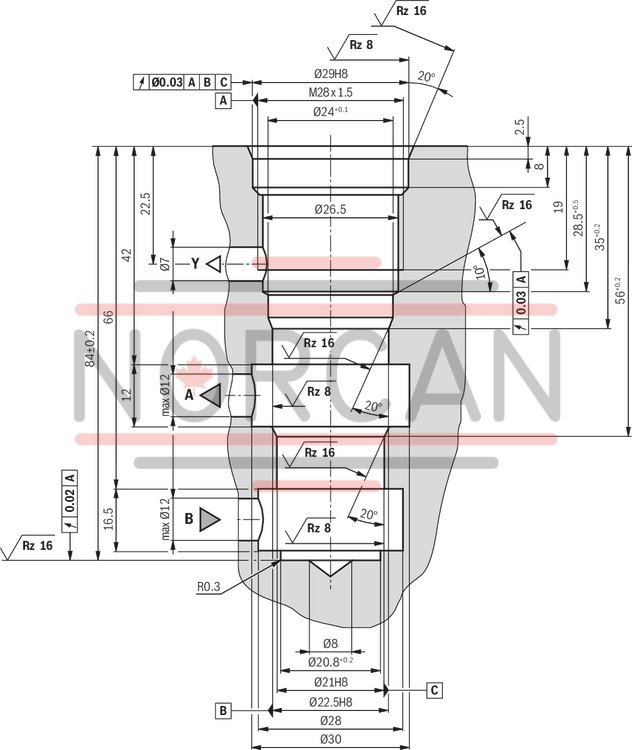
Notice!
Optionally, the connection bores A, B and Y can be applied at the circumference.
Subplates (separate order)
Size 10:G 460/01 (G3/8)
G 461/01 (G1/2)
Size 25:G 412/01 (G3/4)
G 413/01(G1)
Valve mounting screws (separate order)
Size 10:4 hexagon socket head cap screws ISO 4762 - M10 x 40 - 10.9-flZn-240h-L
(friction coefficient μtotal = 0.09 to 0.14);
Tightening torque MA = 75 Nm ± 10 %
Size 25:4 hexagon socket head cap screws ISO 4762 - M10 x 50 - 10.9-flZn-240h-L
(friction coefficient μtotal = 0.09 to 0.14);
Tightening torque MA = 75 Nm ± 10 %
Notice!
The tightening torques stated are guidelines when using screws with the specified friction coefficients and when using a manual torque wrench (tolerance ± 10 %).