
BOSCH REXROTH
R900423255
$1,076.51 USD
- BOSCH REXROTH
- Material:R900423255
- Model:2FRM10-3X/25L
Quantity in stock: 0
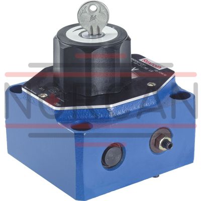
The Bosch Rexroth 2FRM10-3X/25L (R900423255) is a high-performance industrial hydraulic valve designed for precise flow control in hydraulic systems. This mechanically actuated valve offers reliable regulation of flow to a set value, ensuring consistent performance. It comes equipped with a lockable rotary knob featuring a scale that allows for easy and accurate adjustments. With direct actuation and no pressure compensator, the 2FRM10-3X/25L provides efficient operation. It also features stroke limitation, which can be adjusted to suit specific application requirements. The spool symbol A ➝ B, B ➝ A indicates the direction of the throttle control for the hydraulic fluid. This model has a maximum pressure capacity and includes several ports for connectivity, supporting subplate mounting with connection diagrams compliant with ISO standards. Its construction allows it to handle various types of hydraulic fluids including HL, HLP, HLPD, HVLP, HVLPD, and HFC while utilizing NBR seals to maintain integrity under different operating conditions. The 2FRM10-3X/25L valve's design ensures temperature independence due to its orifice bush design at the throttling point. A check valve facilitates free return flow from channel B to channel A without affecting the regulated flow direction from A to B. For applications involving oscillating flows, an additional rectifier sandwich plate type ZS can be installed underneath the valve. In summary, this Bosch Rexroth flow control valve is suitable for applications requiring precise flow management with mechanical actuation and optional stroke limitation features. Its robust design ensures reliable operation even in demanding environments where consistent flow and pressure are critical.
Size 10, A → B, B → A, mechanically actuated
Industrial hydraulic valve in a high performance range. Reliable control of the flow to setting value.
Unpacked Weight: 3.35 kg
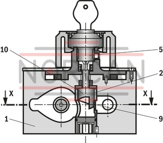
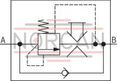
Flow control valves type 2FRM are 2-way flow control valves. They are used to maintain a constant flow, mostly independent of pressure and temperature.
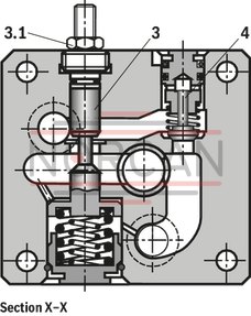
Generally, the valves consist of housing (1), orifice bush (2), pressure compensator (3) with optional stroke limitation (3.1), check valve (4), adjustment element (5) at type 2FRM as well as geared piston drive (6), and directional valve (7). The flow from channel A to channel B is throttled at the throttling point (9). The throttle cross-section of type 2FRM is set by mechanically turning the curved bolt (10) over the adjustment element (5). The positioning velocity can be set by means of the throttle check valve (6.3 and 6.4). To fix the required adjustment range, the geared piston drive (6) is equipped with an adjustable stroke limitation (6.1 and 6.2) on both sides. An upstream pressure compensator (3) is included to ensure a pressure-independent and constant flow at throttling point (9).
Temperature independence is achieved thanks to the orifice design of the throttling point.
The free return flow from channel B to channel A is directed via the check valve (4).
The regulated flow only flows from channel A to B.
For oscillating flows (forward and return flow), a rectifier sandwich plate type Z4S can be installed under the flow control valve.
Type 2 FRM...
Section X–X
| Direct actuated |
| Without pressure compensator stroke limitation |
| Lockable rotary knob with scale |
| Size 10, 16 |
| Maximum flow 160 l/min |
| Maximum operating pressure 315 bar |
| Component series 3X |
| Data Sheet | Download Data Sheet |
| Manual | Download Manual |
| Manual | Download Manual |
| Manual | Download Manual |
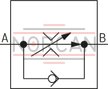
| Spool symbol | A → B, B → A |
| Max. pressure | 315 |
| Productgroup ID | 9,10,11,12,13,14 |
| Number of ports | 2 |
| Type of actuation | with mechanical actuation |
| Size | 10 |
| Max. flow | 25 |
| Type of connection | Subplate mounting |
| Connection diagram | ISO 6263-06-03-*-13 |
| Number of switching positions | 2 |
| Weight | 3.35 |
| Seals | NBR |
| Hydraulic fluid | HL,HLP,HLPD,HVLP,HVLPD,HFC |
|
01 |
02 |
03 |
04 |
05 |
06 |
07 |
08 |
09 |
10 |
11 |
||
|
2FR |
– |
3X |
/ |
* |
|
01 |
2-way flow control valve |
2FR |
|
Type of actuation |
||
|
02 |
Mechanical |
M |
|
Hydraulic |
H |
|
|
Electro-hydraulic |
W |
|
|
03 |
Size 10 |
10 |
|
Size 16 |
16 |
|
|
04 |
Component series 30 ... 39 (30 ... 39: unchanged installation and connection dimensions) |
3X |
|
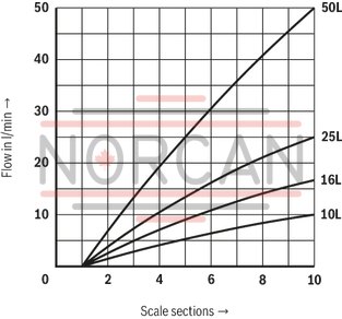
Flow range A to B |
||
|
05 |
Size 10, linear |
|
|
Up to 10 l/min |
10L |
|
|
Up to 16 l/min |
16L |
|
|
Up to 25 l/min |
25L |
|
|
Up to 50 l/min |
50L |
|
|
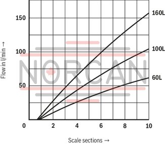
Size 16, linear |
||
|
Up to 60 l/min |
60L |
|
|
Up to 100 l/min |
100L |
|
|
Up to 160 l/min |
160L |
|
|
06 |
Without pressure compensator stroke limitation |
no code |
|
With pressure compensator stroke limitation |
B |
|
|
07 |
Without actual value potentiometer |
no code |
|
With actual value potentiometer (only types 2FRH and 2FRW) |
P |
|
|
08 |
With concealed manual override (standard) |
N9 |
|
With manual override |
N |
|
|
Without manual override |
no code |
|
|
Electrical connection |
||
|
09 |
Individual connection |
|
|
Without mating connector; connector DIN EN 175301-803 |
K4 1) |
|
|
Seal material |
||
|
10 |
NBR seals |
no code |
|
FKM seals |
V |
|
|
Observe compatibility of seals with hydraulic fluid used. |
||
|
11 |
Further details in the plain text |
* |
1) Mating connectors, separate order.
Preferred types and standard units are contained in the EPS (standard price list).
general
|
Size |
10 | 16 | ||
|
Weight |
kg |
5.6 | 11.3 | |
|
Installation position |
any | |||
|
Ambient temperature range |
NBR seals |
°C |
-30 … +80 | |
|
FKM seals |
°C |
-20 … +80 | ||
hydraulic
|
Size |
10 | 16 | |||||||
|
Maximum flow |
l/min |
10 16 25 50 |
60 100 160 |
||||||
|
Maximum operating pressure |
Anschluss A |
bar |
315 | ||||||
|
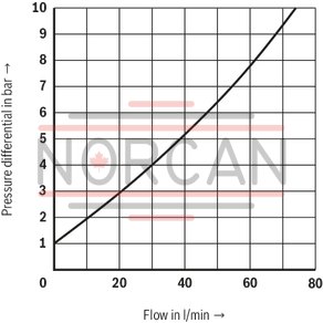
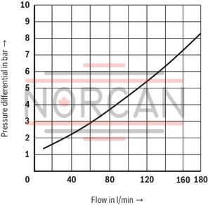
Pressure differential with free return flow B to A, qV-dependent |
bar |
2 | 2.5 | 3.5 | 6 | 2.8 | 4.3 | 7.3 | |
|
Minimum pressure differential |
bar |
3 … 7 | 5 … 12 | ||||||
|
Flow control |
Thermally stable (qV max) at –20 … +80 °C |
% |
± 2 | ||||||
|
Pressure stable (qV max) to Δp = 315 bar |
% |
± 2 | < ± 5 | ||||||
|
Hydraulic fluid |
see table | ||||||||
|
Hydraulic fluid temperature range |
NBR seals |
°C |
-30 … +80 | ||||||
|
FKM seals |
°C |
-20 … +80 | |||||||
|
Viscosity range |
mm²/s |
10 … 800 | |||||||
|
Maximum admissible degree of contamination of the hydraulic fluid 1) |
Class 20/18/15 according to ISO 4406 (c) | ||||||||
| 1) | The cleanliness classes specified for the components must be adhered to in hydraulic systems. Effective filtration prevents faults and simultaneously increases the life cycle of the components. For the selection of the filters, see www.boschrexroth.com/filter. |
|
Hydraulic fluid |
Classification |
Suitable sealing materials |
Standards |
|
|
Mineral oils |
HL, HLP |
NBR, FKM |
DIN 51524 |
|
|
Bio-degradable |
Insoluble in water |
HETG |
NBR, FKM |
VDMA 24568 |
|
HEES |
FKM |
|||
|
Soluble in water |
HEPG |
FKM |
VDMA 24568 |
|
|
Containing water |
Water-free |
HFDU |
FKM |
ISO 12922 |
|
Containing water |
HFC (Fuchs Hydrotherm 46M, Petrofer Ultra Safe 620) |
NBR |
ISO 12922 |
|
|
Important information on hydraulic fluids! For further information and data on the use of other hydraulic fluids, please refer to data sheet 90220 or contact us! There may be limitations regarding the technical valve data (temperature, pressure range, life cycle, maintenance intervals, etc.)! The flash point of the hydraulic fluid used must be 40 K higher than the maximum solenoid surface temperature. Flame-resistant – containing water: Maximum pressure differential per control edge 50 bar. Pressure pre-loading at the tank port >20% of the pressure differential; otherwise, increased cavitation Life cycle compared to operation with mineral oil HL, HLP 50 to 100 % Bio-degradable: When using bio-degradable hydraulic fluids that are zinc-solving, zinc may accumulate in the fluid (700 mg zinc per pole tube) |
||||
electrical ‑ Actual value potentiometer
|
Resistance |
Ω |
1000 |
|
Load capacity |
W |
5 |
|
Maximum wiper current |
A |
0.12 |
|
Protection class according to DIN EN 60529 |
IP65 | |
|
Control limit error at 10°/s (depending on the positioning velocity) |
° |
± 1.5 |
For applications outside these parameters, please consult us!
(measured with HLP46, ϑOil = 40 ±5 °C)
Flow control (A to B)
NG10
Flow control (A to B)
NG16
Free return flow (B to A)
NG10
Free return flow (B to A)
NG16
|
simplified |
Detailed |
|
|
Type 2FRM |
|
|
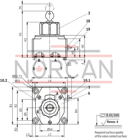
Dimensions in mm
|
NG |
B1 |
B2 |
B3 |
B4 |
B5 |
B6 |
ØD1 |
ØD2 |
D3 |
H1 |
H2 |
H3 |
H4 |
H5 |
L1 |
L2 |
L3 |
L4 |
T1 |
|
mm |
mm |
mm |
mm |
mm |
mm |
mm |
mm |
mm |
mm |
mm |
mm |
mm |
mm |
mm |
mm |
mm |
mm |
mm |
|
| 10 | 101.5 | 82.5 | 9.5 | 68 | 58.7 | 35.5 | 9 | 15 | 6 | 125 | 95 | 26 | 51 | 60 | 95 | 76 | 9.5 | 79.4 | 13 |
| 16 | 123.5 | 101.5 | 11 | 81.5 | 72.5 | 41.5 | 11 | 18 | 6 | 147 | 117 | 34 | 72 | 82 | 123.5 | 101.5 | 11 | 102.4 | 12 |
Subplates (separate order)
Size 10:
G 279/01 (G 1/2)
G 280/01 (G 3/4)
Size 16:
G 281/01 (G 1)
G 282/01 (G 1 1/4)
Valve mounting screws (separate order)
Size 10:4 hexagon socket head cap screws ISO 4762 - M8 x 50 - 10.9-flZn-240h-L
(friction coefficient μtotal = 0.09 to 0.14);
Tightening torque MA = 30 Nm ± 10 %,
Material no. R913000543
Size 16:4 hexagon socket head cap screws ISO 4762 - M10 x 80 - 10.9-flZn-240h-L
(friction coefficient μtotal = 0.09 to 0.14);
Tightening torque MA = 64 Nm ±10 %,
Material no. R913000496
Mating connectors for valves with connector “K4”, without circuitry, standard
3P Z4
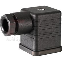
Mating connectors for valves with connector “K4”, without circuitry, standard
3P Z4
For valves with connector “K4” according to EN 175301-803 and ISO 4400, 2-pole + PE, “large cubic connector” Mating connectors for valves with one or two solenoids (individual connection)Data sheet
Spare parts & repair
Mating connectors for valves with connector “K4”, with indicator light
3P Z5L
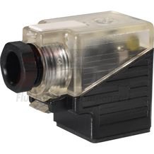
Mating connectors for valves with connector “K4”, with indicator light
3P Z5L
For valves with connector “K4” according to EN 175301-803 and ISO 4400, 2-pole + PE, “large cubic connector” Mating connectors for valves with one or two solenoids (individual connection)Data sheet
Spare parts & repair
Mating connectors for valves with connector “K4”, with indicator light and Zener diode suppression circuit
3P Z5L1
Mating connectors for valves with connector “K4”, with indicator light and Zener diode suppression circuit
3P Z5L1
For valves with connector “K4” according to EN 175301-803 and ISO 4400, 2-pole + PE, “large cubic connector” Mating connectors for valves with one or two solenoids (individual connection)Data sheet
Spare parts & repair
Mating connectors for valves with connector “K4”, with rectifier
3P RZ5
Mating connectors for valves with connector “K4”, with rectifier
3P RZ5
For valves with connector “K4” according to EN 175301-803 and ISO 4400, 2-pole + PE, “large cubic connector” Mating connectors for valves with one or two solenoids (individual connection)Data sheet
Spare parts & repair