

BOSCH REXROTH
R900438124
- BOSCH REXROTH
- Material:R900438124
- Model:DB 10 K3-4X/315YV
Due to extremely high demand, please call 877-366-7226 for availability
The Bosch Rexroth DB 10 K3-4X/315YV (R900438124) is a high-performance screw-in cartridge valve designed to function as a pilot-operated pressure relief valve for block design installation, primarily used for system pressure limitation. This valve belongs to the DB.K product family classification and is identified by its ability to handle a maximum operating pressure of 315 bar (4568 psi) and a maximum flow of up to NG10 l/min. It features an Mx cavity and utilizes FKM as its sealing material, ensuring reliable performance under various conditions. The DB 10 K3-4X/315YV valve's capabilities include an internal pilot oil supply and external pilot oil return, with a poppet-type spool that responds to changes in system pressure. The adjustment options for this model include a lockable rotary knob with scale, allowing precise control over the system pressure settings. Designed with pilot-operated functionality, this relief valve maintains the desired pressure level by opening the connection from main port A to B when the set value is exceeded. The counter pressures at main port A are considered in setting the system pressure, contributing to the valve's efficiency and safety in operation. Compatible with hydraulic fluids such as HL, HLP, HEES, and HEPG, the Bosch Rexroth DB 10 K3-4X/315YV ensures versatility across various hydraulic applications while maintaining superior quality standards synonymous with Bosch Rexroth's engineering expertise. The product's robust construction and reliability make it suitable for demanding applications where precise pressure control is essential.
Unpacked Weight: 0.45 kg
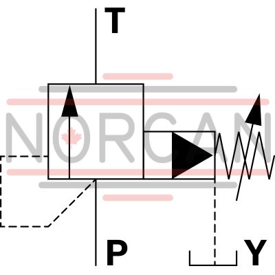
Pressure valves type DB..K.. are pilot-operated pressure relief valves for block design installation. They are used for system pressure limitation. The system pressure can be set via the adjustment type (4).
In the initial position the valves are closed. The pressure in main port 1 acts on the spool (1). At the same time, pressure is applied to the spring-loaded side of the spool (1) via nozzle (2) and to the pilot poppet (6) via nozzle (3). If the pressure in main port 1 exceeds the value set at spring (5), the pilot poppet (6) opens. Hydraulic fluid flows from the spring-loaded side of the spool (1) via nozzle (3) and channel (7) into the main port 3. The resulting pressure drop moves the spool (1) and thus opens the connection from main port 1 to 2 while maintaining the pressure set at spring (5).
Die pilot oil return from the two spring chambers is effected externally, via main port 3.
Notice!
Counter pressures (main port 3) add up to the set pressure.
Type DB 10 K2-4X/.YV

| Screw-in cartridge valve |
| Maximum operating pressure 315 bar (4568 psi) |
| Maximum flow 100 l/min (26 gpm) |
| Cavity M24x1 |
| Max. pressure | 315 |
| Adjustment options | Lockable rotary knob with scale |
| Product family classification | Pressure relief valve, pilot operated |
| Productgroup ID | 9,10,11,12,13,14 |
| Product family type | DB.K |
| Ports number | 3 |
| Sealing material | FKM |
| Cavity | M24x1 |
| Product type | DB.K |
| Max. flow | 100 |
| Type of connection | Screw-in cartridge valve |
| Nominal flow | 100 |
| Direct - Pilot | Pilot operated |
| Product family | Relief |
| Pilot oil supply and return | Internal pilot oil supply, external pilot oil return |
| Spool Poppet | Poppet type |
| Weight | 0.45 |
| Hydraulic fluid | HL,HLP,HEES,HEPG |
|
01 |
02 |
03 |
04 |
05 |
06 |
07 |
08 |
09 |
||
|
DB |
K |
– |
4X |
/ |
Y |
V |
* |
|
01 |
Pressure relief valve, pilot controlled |
DB |
|
02 |
Size 6 |
6 |
|
Size 10 |
10 |
|
|
03 |
Cartridge valve |
K |
|
Adjustment type |
||
|
04 |
Rotary knob |
1 |
|
Sleeve with hexagon and protective cap |
2 |
|
|
Lockable rotary knob with scale |
3 1) |
|
|
Rotary knob with scale |
7 |
|
|
05 |
Component series 40 … 49 (40 … 49: unchanged installation and mounting dimensions) |
4X |
|
Pressure rating |
||
|
06 |
Set pressure up to 50 bar |
50 |
|
Set pressure up to 100 bar |
100 |
|
|
Set pressure up to 200 bar |
200 |
|
|
Set pressure up to 315 bar |
315 |
|
|
07 |
Internal pilot oil supply, external pilot oil return |
Y |
|
Seal material |
||
|
08 |
FKM seals (other seals upon request) |
V |
|
Observe compatibility of seals with hydraulic fluid used. |
||
|
09 |
Further details in the plain text |
* |
| 1) H-key with material no. R900008158 is included in the scope of delivery. |
general
|
Size |
6 | 10 | |
|
Weight (approx.) |
kg |
0.15 | 0.2 |
|
Installation position |
any | ||
|
Ambient temperature range |
°C |
-20 … +80 | |
hydraulic
|
Size |
6 | 10 | ||
|
Maximum operating pressure 1) |
Port P |
bar |
315 | |
|
Maximum adm. counter pressure 1) |
Port T |
bar |
315 | |
|
Port Y |
bar |
315 | ||
|
Maximum set pressure |
Port P |
bar |
50 100 200 315 |
|
|
Maximum flow |
l/min |
60 | 100 | |
|
Hydraulic fluid |
see table | |||
|
Hydraulic fluid temperature range |
°C |
-20 … +80 | ||
|
Viscosity range |
mm²/s |
10 … 800 | ||
|
Maximum admissible degree of contamination of the hydraulic fluid 2) |
Class 20/18/15 according to ISO 4406 (c) | |||
| 1) | Attention! The maximum operating pressure is added up from the set pressure and the return flow pressure. |
| 2) | The cleanliness classes specified for the components must be adhered to in hydraulic systems. Effective filtration prevents faults and simultaneously increases the life cycle of the components. For the selection of the filters, see www.boschrexroth.com/filter. |
|
Hydraulic fluid |
Classification |
Suitable sealing materials |
Standards |
|
|
Mineral oil |
HL, HLP |
FKM, NBR |
DIN 51524 |
|
|
Bio-degradable |
Insoluble in water |
HEES (synthetic esters) |
FKM |
VDMA 24568 |
|
HETG (rape seed oil) |
FKM, NBR |
|||
|
Soluble in water |
HEPG (polyglycols) |
FKM |
VDMA 24568 |
|
|
Other hydraulic fluids on request |
||||
For applications outside these parameters, please consult us!
(measured with HLP46, ϑOil = 40 ±5 °C)
NG6
pE-qV characteristic curves

NG6
pE min-qV characteristic curves

Attention!
The characteristic curves apply for output pressure = zero in the entire flow range!
NG10
pE-qV characteristic curves

NG10
pE min-qV characteristic curves


|
➀ |
Main port 1 (P) |
|
➁ |
Main port 2 (T) |
|
➂ |
Main port 3 (Y) |
NG6
Dimensions in mm

|
1 |
Adjustment type "1" |
|
2 |
Adjustment type "2" |
|
3 |
Adjustment type "3" |
|
4 |
Adjustment type "7" |
|
5 |
Space required to remove the key |
|
6 |
Lock nut SW24 |
|
7 |
Hexagon SW10 |
|
8 |
Wrench size SW24, tightening torque for screw-in MA = 50 Nm |
|
➀ |
Main port 1 (P) |
|
➁ |
Main port 2 (T) |
|
➂ |
Main port 3 (Y) |
|
LS |
Location shoulder |
|
➀ |
Main port 1 (P) |
|
➁ |
Main port 2 (T), can optionally be arranged at the circumference |
|
➂ |
Main port 3 (Y) |
|
LS |
Location shoulder |
NG6; 3 main ports; thread M20 x 1
Dimensions in mm

|
1 |
Adjustment type "1" |
|
2 |
Adjustment type "2" |
|
3 |
Adjustment type "3" |
|
4 |
Adjustment type "7" |
|
5 |
Space required to remove the key |
|
6 |
Lock nut SW24 |
|
7 |
Hexagon SW10 |
|
8 |
Wrench size SW24, tightening torque for screw-in MA = 50 Nm |
|
➀ |
Main port 1 (P) |
|
➁ |
Main port 2 (T) |
|
➂ |
Main port 3 (Y) |
|
LS |
Location shoulder |
|
➀ |
Main port 1 (P) |
|
➁ |
Main port 2 (T), can optionally be arranged at the circumference |
|
➂ |
Main port 3 (Y) |
|
LS |
Location shoulder |
NG10
Dimensions in mm

|
1 |
Adjustment type "1" |
|
2 |
Adjustment type "2" |
|
3 |
Adjustment type "3" |
|
4 |
Adjustment type "7" |
|
5 |
Space required to remove the key |
|
6 |
Lock nut SW24 |
|
7 |
Hexagon SW10 |
|
8 |
Hexagon SW30, tightening torque for screw-in MA = 50 Nm |
|
➀ |
Main port 1 (P) |
|
➁ |
Main port 2 (T) |
|
➂ |
Main port 3 (Y) |
|
LS |
Location shoulder |
Mounting cavity – NG10; 3 main ports; thread M20 x 1
Dimensions in mm

|
➀ |
Main port 1 (P) |
|
➁ |
Main port 2 (T), can optionally be arranged at the circumference |
|
➂ |
Main port 3 (Y) |
|
LS |
Location shoulder |