

BOSCH REXROTH
R900438885
$366.14 USD
- BOSCH REXROTH
- Material:R900438885
- Model:MG8G1X/V
Quantity in stock: 0
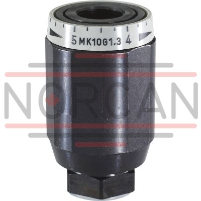
The Bosch Rexroth MG8G1X/V (R900438885) is a high-performance industrial hydraulic valve designed for reliable flow limitation at selected ports to a predetermined setting value. This direct-actuated seat valve falls under the component series X and features a spool symbol A B, indicating its specific flow pattern. It is capable of handling a maximum pressure, although the exact value is not specified here. With its threaded connection type, this valve offers ease of installation and maintenance. It is mechanically actuated, which ensures consistent performance in various industrial applications. The MG8G1X/V valve is equipped to manage a max flow rate, and its design includes a number of ports for versatile connectivity options. The weight of the valve indicates its robustness and suitability for pipeline installation in demanding environments. Furthermore, it utilizes FKM seals which are known for their chemical resistance and durability across a wide range of temperatures. This makes it compatible with an array of hydraulic fluids including HL, HLP, HLPD, HVLP, HVLPD, HETG, HEES, HEPG, HFDU, HFDR. The MG series valves are characterized by their pressure and viscosity-dependent throttle capabilities which enable throttling in both directions of flow. The hydraulic fluid's path to the throttling point involves lateral bores that lead to an adjustable sleeve housed within the unit; by rotating this sleeve the user can seamlessly adjust the cross-section at the throttling point for precise control. Designed with corrosion protection in mind, this Bosch Rexroth valve ensures longevity even in harsh working conditions. Its size and series designation reflect its capacity to integrate into various industrial systems where precise flow regulation is critical.
Size 8, A → B, mechanically actuated
Industrial hydraulic valve in a high performance range. Reliable flow limitation at selected ports to setting value.
Unpacked Weight: 0.34 kg
The valves type MG are pressure- and viscosity-dependent throttle valves.
Throttling is realized in both directions of flow. The hydraulic fluid is directed to the throttling point (4) via lateral bores (3). It is formed between the housing (2) and the adjustable sleeve (1). By rotating the sleeve (1), the cross-section of the throttling point (4) can be steplessly adjusted.

| Seat valve |
| Direct actuated |
| Component series 1X |
| Maximum operating pressure 315 bar |
| Size 6 … 30 |
| Maximum flow 400 l/min |
| Data Sheet | Download Data Sheet |
| Manual | Download Manual |
| Manual | Download Manual |
| Manual | Download Manual |
| Manual | Download Manual |
| Manual | Download Manual |
| Spool symbol | A → B |
| Max. pressure | 315 |
| Productgroup ID | 9,10,11,12,13,14 |
| Number of ports | 2 |
| Type of actuation | with mechanical actuation |
| Size | 8 |
| Max. flow | 40 |
| Type of connection | Threaded connection |
| Connection diagram | Pipe thread G3/8 ISO 228-1 |
| Number of switching positions | 2 |
| Weight | 0.34 |
| Seals | FKM |
| Hydraulic fluid | HL,HLP,HLPD,HVLP,HVLPD,HETG,HEES,HEPG,HFDU,HFDR |
|
01 |
02 |
03 |
04 |
05 |
06 |
07 |
|
|
MG |
G |
1X |
/ |
* |
|
01 |
Throttle valve |
MG |
|
02 |
Size 6 |
6 |
|
Size 8 |
8 |
|
|
Size 10 |
10 |
|
|
Size 15 |
15 |
|
|
Size 20 |
20 |
|
|
Size 25 |
25 |
|
|
Size 30 |
30 |
|
|
03 |
For threaded connection |
G |
|
04 |
Component series 10 ... 19 (10 ... 19: unchanged installation and connection dimensions) |
1X |
|
Corrosion resistance (outside) |
||
|
05 |
None (valve housing primed) |
no code |
|
Improved corrosion protection (240 h salt spray test according to EN ISO 9227) |
J3 |
|
|
Improved corrosion protection (720 h salt spray test according to EN ISO 9227) |
J5 |
|
|
Seal material (observe compatibility of seals with hydraulic fluid used, see "Technical data") |
||
|
06 |
NBR seals |
no code |
|
FKM seals |
V |
|
|
07 |
Further details in the plain text |
* |
Notice:
For valve types for use in potentially explosive areas, refer to data sheet 07011.
general
|
Size |
6 | 8 | 10 | 15 | 20 | 25 | 30 | ||
|
Weight |
kg |
0.3 | 0.4 | 0.7 | 1.1 | 1.9 | 3.2 | 4.1 | |
|
Installation position |
any | ||||||||
|
Ambient temperature |
NBR seals |
°C |
-30 … +80 | ||||||
|
FKM seals |
°C |
-20 … +80 | |||||||
hydraulic
|
Size |
6 | 8 | 10 | 15 | 20 | 25 | 30 | ||
|
Maximum operating pressure |
bar |
315 | |||||||
|
Maximum flow |
See characteristic curves | ||||||||
|
Leakage flow 1) |
Standard |
l/min |
0.8 | 1 | 2 | 3 | 4 | 5.5 | |
|
Version "J3" and "J5" |
l/min |
1.6 | 2.5 | 3.2 | 3.5 | 7 | 7.7 | ||
|
Hydraulic fluid |
see table "Hydraulic fluid" | ||||||||
|
Hydraulic fluid temperature range |
NBR seals |
°C |
-30 … +80 | ||||||
|
FKM seals |
°C |
-20 … +80 | |||||||
|
Viscosity range |
mm²/s |
10 … 800 | |||||||
|
Maximum admissible degree of contamination of the hydraulic fluid, cleanliness class according to ISO 4406 (c) 2) |
Class 20/18/15 | ||||||||
|
Load cycles |
million |
10 | 2 | ||||||
| 1) | If valve is completely closed |
| 2) | The cleanliness classes specified for the components must be adhered to in hydraulic systems. Effective filtration prevents faults and simultaneously increases the life cycle of the components. For the selection of the filters, see www.boschrexroth.com/filter. |
|
Hydraulic fluid |
Classification |
Suitable sealing materials |
Standards |
Data sheet |
|
|
Mineral oils |
HL, HLP |
NBR, FKM |
DIN 51524 |
90220 |
|
|
Bio-degradable 1) |
Insoluble in water |
HETG |
FKM |
ISO 15380 |
90221 |
|
HEES |
FKM |
||||
|
Soluble in water |
HEPG |
FKM |
ISO 15380 |
||
|
Flame-resistant |
Water-free |
HFDU (glycol base) |
FKM |
ISO 12922 |
90222 |
|
HFDU (ester base) 1) |
FKM |
||||
|
HFDR |
FKM |
||||
|
Containing water 1) |
HFC (Fuchs Hydrotherm 46M, Fuchs Renosafe 500, Petrofer Ultra Safe 620, Houghton Houghto Safe 620, Union Carbide HP5046) |
NBR |
ISO 12922 |
90223 |
|
|
Important information on hydraulic fluids: For more information and data on the use of other hydraulicfluids, please refer to the data sheets above or contact us. There may be limitations regarding the technical valve data (temperature, pressure range, life cycle, maintenance intervals, etc.). The ignition temperature of the hydraulic fluid used must be 50 K higher than the maximum surface temperature. Flame-resistant - containing water: Maximum pressure differential 210 bar, otherwise, increased cavitation erosion Life cycle as compared to operation with mineral oil HL, HLP 30 … 100%. Maximum hydraulic fluid temperature 60 °C Bio-degradable and flame-resistant – containing water: If this hydraulic fluid is used, small amounts of dissolved zinc may get into the hydraulic system. |
|||||
| 1) | Not recommended for corrosion-protected version "J3" and "J5" (contains zinc) |
For applications outside these parameters, please consult us!
(measured with HLP46, ϑOil = 40 ±5 °C)
Δp-qV characteristic curves via open throttle

Δp-qV characteristic curves via open throttle

Type MG

Dimensions in mm

|
1 |
Valve marking on key face |
|
NG |
D1 |
ØD2 |
L |
SW1 |
SW2 |
T |
|
mm |
mm |
mm |
mm |
mm |
||
| 6 | G1/4 | 34 | 65 | 22 | 32 | 12 |
| 8 | G3/8 | 38 | 65 | 24 | 36 | 12 |
| 10 | G1/2 | 48 | 80 | 30 | 46 | 14 |
| 15 | G3/4 | 58 | 100 | 41 | 55 | 16 |
| 20 | G1 | 72 | 110 | 46 | 70 | 18 |
| 25 | G1 1/4 | 87 | 130 | 55 | 85 | 20 |
| 30 | G1 1/2 | 93 | 150 | 60 | 90 | 22 |