
BOSCH REXROTH
R900456783
$1,403.67 USD
- BOSCH REXROTH
- Material:R900456783
- Model:Z2FS 22-8-3X/S
Quantity in stock: 0
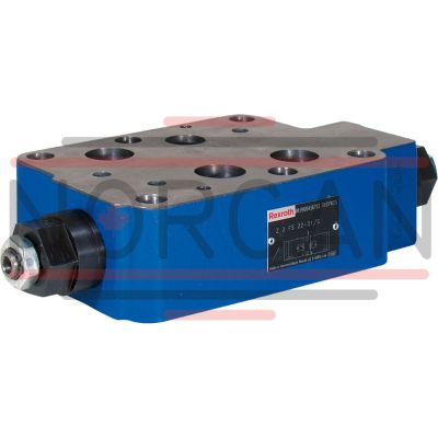
The Bosch Rexroth Z2FS22-8-3X/S (R900456783) is a high-performance industrial hydraulic valve designed for reliable flow throttling to a set value. This valve features a size CETOP D sandwich plate connection, conforming to ISO and NFPA T.. R D standards, ensuring compatibility with a wide range of systems. The Z2FS22-8-3X/S is a mechanically actuated throttle check valve, equipped with an internal hexagon spindle for precise adjustment. With its dual throttle check valves, the Z2FS22-8-3X/S is capable of limiting the flow in one direction while allowing free return flow in the opposite direction. This functionality makes it suitable for controlling actuator speeds by adjusting the main or pilot flow at two consumer ports. The valve's spool symbol can be configured as A A, B B or A A, B B, depending on the application requirements. The maximum operating pressure for this model is indicated by its product group ID and it supports a maximum flow rate as specified in its technical data. The type of actuation is mechanical, which ensures direct and responsive control over the throttling process. Its corrosion-protected design adds to its durability in harsh industrial environments. Seals made from NBR (Nitrile Butadiene Rubber) are used within this model, making it suitable for use with various hydraulic fluids including HL, HLP, HLPD, HVLP, HVLPD, and HFC types. The weight of the valve provides an indication of its robustness and suitability for industrial applications. In summary, the Bosch Rexroth Z2FS22-8-3X/S offers precise control over fluid flow in hydraulic systems through its adjustable throttle spools and mechanical actuation. Its adherence to international standards for size and connection patterns ensures ease of integration into existing setups or new installations where regulation of actuator velocity is required.
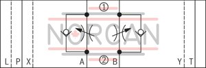
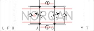
Size 25, A1 → A2, B1 → B2 or A2 → A1, B2 → B1, mechanically actuated
Industrial hydraulic valve in a high performance range. Reliable throttling of the flow to setting value.
Unpacked Weight: 6.76 kg
The valve type Z2FS is a throttle check valve in sandwich plate design. It is used for the flow limitation of one or two actuator ports.
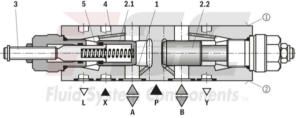
Two symmetrically arranged throttle check valves limit flows (by adjustable throttle spools) in one direction and allow free return flow in the opposite direction.
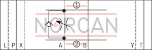
In case of supply throttling, the hydraulic fluid is directed through channel A➀ via throttling point (1) to actuator A➁. The throttle spool (2.1) can be axially adjusted via the spindle (3) for adjustment of the throttling point (1).
Simultaneously, the hydraulic fluid in channel A➀ is directed via the bore (4) to the piston side (5). The active pressure and the spring force retain the throttle spool (2.1) in throttle position.
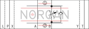
The hydraulic fluid return flow from actuator B➁ displaces the throttle spool (2.2) and enables the unobstructed flow as check valve. Depending on the version ("S" or "S2"), the throttling effect may occur in supply or discharge.
Flow limitation
For actuator velocity adjustment, the throttle check valve is installed between the directional valve and the subplate.
Supply throttling
|
① |
component side |
|
② |
plate side |
| Direct actuated |
| Internal hexagon |
| Component series 3X |
| Size 25 |
| Maximum operating pressure 350 bar |
| Maximum flow 360 l/min |
| Data Sheet | Download Data Sheet |
| 3D CAD | Download 3D CAD |
| Manual | Download Manual |
| Manual | Download Manual |
| Manual | Download Manual |
| Manual | Download Manual |
| Manual | Download Manual |
| Spool symbol | A1 → A2, B1 → B2 or A2 → A1, B2 → B1 |
| Max. pressure | 350 |
| Productgroup ID | 9,10,11,12,13,14 |
| Number of ports | 4 |
| Type of actuation | with mechanical actuation |
| Size | 25 |
| Max. flow | 360 |
| Type of connection | Sandwich plate |
| Connection diagram NFPA | NFPA T3.5.1 R2-2002 D08 |
| Size_CETOP | D08 |
| Connection diagram | ISO 4401-08-08-0-05 |
| Number of switching positions | 2 |
| Weight | 6.76 |
| Seals | NBR |
| Hydraulic fluid | HL,HLP,HLPD,HVLP,HVLPD,HFC |
|
01 |
02 |
03 |
04 |
05 |
06 |
07 |
08 |
09 |
||
|
Z2FS |
22 |
8 |
– |
3X |
/ |
* |
|
01 |
Throttle check valve, sandwich plate design |
Z2FS |
|
02 |
Size 25 |
22 |
|
03 |
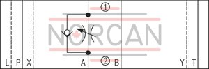
Throttle check valve side A and B |
– |
|
Throttle check valve side A |
A |
|
|
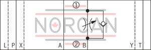
Throttle check valve side B |
B |
|
|
Adjustment type |
||
|
04 |
Spindle with internal hexagon |
8 |
|
05 |
Component series 30 ... 39 (30 ... 39: unchanged installation and connection dimensions) |
3X |
|
06 |
Supply throttling |
S |
|
Discharge throttling |
S2 |
|
|
Corrosion resistance (outside) |
||
|
07 |
None (valve housing primed) |
no code |
|
Improved corrosion protection (240 h salt spray test according to EN ISO 9227) |
J3 |
|
|
Seal material |
||
|
08 |
NBR seals |
no code |
|
FKM seals |
V |
|
|
Observe compatibility of seals with hydraulic fluid used. (Other seals upon request) |
||
|
09 |
Further details in the plain text |
* |
general
|
Size |
25 | ||
|
Weight (approx.) |
kg |
8 | |
|
Installation position |
any | ||
|
Ambient temperature range |
NBR seals |
°C |
-30 … +50 |
|
FKM seals |
°C |
-20 … +50 | |
hydraulic
|
Size |
25 | ||
|
Maximum operating pressure |
bar |
350 | |
|
Maximum flow |
l/min |
360 | |
|
Hydraulic fluid |
see table | ||
|
Hydraulic fluid temperature range |
NBR seals |
°C |
-30 … +80 |
|
FKM seals |
°C |
-20 … +50 | |
|
Viscosity range |
mm²/s |
2.8 … 380 | |
|
Maximum admissible degree of contamination of the hydraulic fluid, cleanliness class according to ISO 4406 (c) 1) |
Class 20/18/15 | ||
| 1) | The cleanliness classes specified for the components must be adhered to in hydraulic systems. Effective filtration prevents faults and simultaneously increases the life cycle of the components. For the selection of the filters, see www.boschrexroth.com/filter. |
|
Hydraulic fluid |
Classification |
Suitable sealing materials |
Standards |
Data sheet |
|
|
Mineral oils |
HL, HLP, HLPD, HVLP, HVLPD |
NBR, FKM |
DIN 51524 |
90220 |
|
|
Bio-degradable |
Insoluble in water |
HETG 1) |
NBR, FKM |
ISO 15380 |
90221 |
|
HEES 1) |
FKM |
||||
|
Soluble in water |
HEPG 1) |
FKM |
ISO 15380 |
||
|
Flame-resistant |
Water-free |
HFDU (glycol base) |
FKM |
ISO 12922 |
90222 |
|
HFDU (ester base) 1) |
FKM |
||||
|
HFDR |
FKM |
||||
|
Containing water |
HFC (Fuchs Hydrotherm 46M, Petrofer Ultra Safe 620) 1) |
NBR |
ISO 12922 |
90223 |
|
|
Important information on hydraulic fluids: For more information and data on the use of other hydraulicfluids, please refer to the data sheets above or contact us. There may be limitations regarding the technical valve data (temperature, pressure range, life cycle, maintenance intervals, etc.). The ignition temperature of the hydraulic fluid used must be 50 K higher than the maximum surface temperature. Flame-resistant - containing water: Maximum pressure differential 210 bar, otherwise, increased cavitation erosion Life cycle as compared to operation with mineral oil HL, HLP 30 … 100%. Maximum hydraulic fluid temperature 60 °C Bio-degradable and flame-resistant – containing water: If this hydraulic fluid is used, small amounts of dissolved zinc may get into the hydraulic system. |
|||||
| 1) | Not recommended for corrosion-protected version "J3" (contains zinc) |
For applications outside these parameters, please consult us!
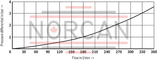
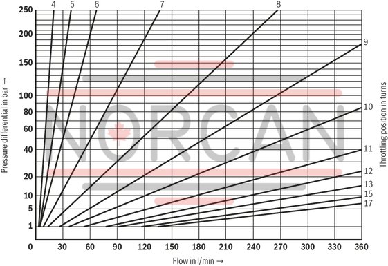
(measured with HLP46, ϑOil = 40 ±5 °C)
Δp-qV characteristic curves
Via check valve with closed throttle
Δp-qV characteristic curves
Constant throttle position
|
① |
component side |
|
② |
plate side |
Supply throttling "S"
Version "-"
Version "A"
Version "B"
Discharge throttling "S2"
Version "-"
Version "A"
Version "B"
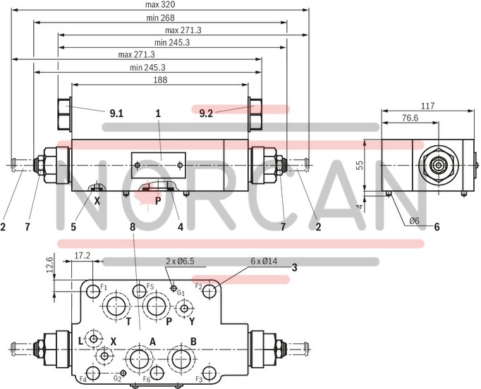
Dimensions in mm
|
|
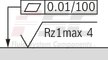
Required surface quality of the valve contact surface |
|
1 |
Name plate |
|
2 |
Adjustment type "8“ Spindle for changing the flow cross-section (internal hexagon SW6) Left rotation = higher flow Right rotation = lower flow |
|
3 |
Through holes for valve mounting |
|
4 |
Same seal rings for ports A, B, P, T |
|
5 |
Identical seal rings for ports X, Y, L |
|
6 |
Locking pin (included in the scope of delivery) |
|
7 |
Hexagon SW22, tightening torque MA = 25 Nm |
|
8 |
Porting pattern according to ISO 4401-08-08-0-05 |
|
9.1 |
Plug screw with version "B" |
|
9.2 |
Plug screw with version "A" |
Valve mounting screws (separate order)
|
Size |
Quantity |
Hexagon socket head cap screws |
Material number |
|
25 |
6 |
ISO 4762 - M12 - 10.9-flZn-240h-L |
- |
Notice:
Length and tightening torque of the valve mounting screws must be calculated according to the components mounted under and over the sandwich plate valve.