

BOSCH REXROTH
R900469827
- BOSCH REXROTH
- Material:R900469827
- Model:DR 10 K4-3X/315YMV
Due to extremely high demand, please call 877-366-7226 for availability
The Bosch Rexroth DR 10 K4-3X/315YMV (R900469827) is a screw-in cartridge valve designed for use as a pilot-operated pressure reducing valve in block design installations. This model is part of the DR.K product family, which specializes in pressure reduction applications. It features a poppet type spool and operates under a maximum pressure of 315 bar (4569 psi), with a nominal flow rate capacity. The valve is engineered to maintain a secondary system pressure that can be adjusted using the rotary knob provided. In its normal position, the DR 10 K4-3X/315YMV valve allows hydraulic fluid to flow unrestricted from port A to port B. The secondary pressure setting is achieved through an internal pilot oil supply and external pilot oil return system, ensuring consistent performance. The valve's operation depends on the balance of forces between the main spool and the pilot poppet, which responds to changes in system pressure to maintain the desired setting. The DR 10 K4-3X/315YMV has been constructed with FKM sealing material for compatibility with various hydraulic fluids including HL, HLP, HEES, and HEPG types. Its design includes multiple ports for flexible installation options within hydraulic systems. Additionally, it offers various adjustment options such as a sleeve with hexagon and protective cap or lockable rotary knob with scale, catering to different operational requirements. This model ensures reliable performance in maintaining system pressures within hydraulic circuits while providing ease of adjustment for operators. Its robust construction and thoughtful design make it suitable for varied applications where precise pressure control is essential.
Unpacked Weight: 0.38 kg
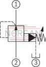
Pressure valves type DR 10 K.. are pilot-operated pressure reducing valves for block design installation. They are used for reducing a system pressure. The secondary pressure is set via the adjustment type (4).
In initial position, the valves are open. Hydraulic fluid can flow from main port 2 to 1 without restrictions. The pressure in main port 1 acts simultaneously at main spool (1) and via the nozzle (2) at the spring-loaded inside of the main spool (1). Similarly, it acts via nozzle (7) on the pilot poppet (8). If the pressure in main port 1 exceeds the value set at spring (5), the pilot poppet (8) opens. Hydraulic fluid flows from the chamber of spring (3) via the nozzle (7), the pilot poppet (8) and the spring chamber (6) into main port 3. The main spool (1) assumes its control position and keeps the value in main port 1 set at the spring (5) constant.
The pilot oil return from the spring chamber (6) is always realized externally via main port (3).
Notice!
Counter pressures (main port 3) add up to the set pressure.
Type DR 10 K5-3X/.YM

| Screw-in cartridge valve |
| Maximum operating pressure 350 bar (5000 psi) |
| Maximum flow 100 l/min (26 gpm) |
| Cavity M24x1 |
| Max. pressure | 350 |
| Adjustment options | Rotary knob |
| Product family classification | Pressure reducing valve, pilot operated |
| Productgroup ID | 9,10,11,12,13,14 |
| Product family type | DR.K |
| Ports number | 3 |
| Sealing material | FKM |
| Cavity | M24x1 |
| Product type | DR.K |
| Max. flow | 100 |
| Type of connection | Screw-in cartridge valve |
| Normal position | Normally open |
| Nominal flow | 100 |
| Direct - Pilot | Pilot operated |
| Product family | Reducing |
| Pilot oil supply and return | Internal pilot oil supply, external pilot oil return |
| Spool Poppet | Poppet type |
| Weight | 0.38 |
| Hydraulic fluid | HL,HLP,HEES,HEPG |
|
01 |
02 |
03 |
04 |
05 |
06 |
07 |
08 |
09 |
10 |
||
|
DR |
10 |
K |
– |
3X |
/ |
Y |
M |
* |
|
01 |
Pressure reducing valve, pilot-operated |
DR |
|
02 |
Size 10 |
10 |
|
03 |
Cartridge valve |
K |
|
Adjustment type |
||
|
04 |
Rotary knob |
4 |
|
Sleeve with hexagon and protective cap |
5 |
|
|
Lockable rotary knob with scale |
6 1) |
|
|
Rotary knob with scale |
7 |
|
|
05 |
Component series 30 ... 39 (30 ... 39: unchanged installation and connection dimensions) |
3X |
|
Pressure rating |
||
|
06 |
Secondary pressure up to 50 bar |
50 |
|
Secondary pressure up to 100 bar |
100 |
|
|
Secondary pressure up to 200 bar |
200 |
|
|
Secondary pressure up to 315 bar |
315 |
|
|
07 |
Internal pilot oil supply, external pilot oil return |
Y |
|
08 |
Without check valve |
M |
|
Seal material |
||
|
09 |
NBR seals |
no code |
|
FKM seals (other seals upon request) |
V |
|
|
Observe compatibility of seals with hydraulic fluid used. |
||
|
10 |
Further details in the plain text |
* |
| 1) H-key with material no. R900008158 is included in the scope of delivery. |
general
|
Size |
10 | ||
|
Weight |
kg |
0.2 | |
|
Installation position |
any | ||
|
Ambient temperature range |
NBR seals |
°C |
-30 … +80 |
|
FKM seals |
°C |
-20 … +80 | |
hydraulic
|
Size |
10 | ||
|
Maximum operating pressure 1) |
Main port 2 (P) |
bar |
315 |
|
Secondary pressure |
Main port 1 (A) |
bar |
50 100 200 315 |
|
Maximum adm. counter pressure 1) |
Main port 3 (T) |
bar |
315 |
|
Maximum flow |
l/min |
100 | |
|
Hydraulic fluid |
see table | ||
|
Hydraulic fluid temperature range |
NBR seals |
°C |
-30 … +80 |
|
FKM seals |
°C |
-20 … +80 | |
|
Viscosity range |
mm²/s |
10 … 800 | |
|
Maximum admissible degree of contamination of the hydraulic fluid 2) |
Class 20/18/15 according to ISO 4406 (c) | ||
| 1) | Attention! The maximum operating pressure is added up from the set pressure and the return flow pressure. |
| 2) | The cleanliness classes specified for the components must be adhered to in hydraulic systems. Effective filtration prevents faults and simultaneously increases the life cycle of the components. For the selection of the filters, see www.boschrexroth.com/filter. |
|
Hydraulic fluid |
Classification |
Suitable sealing materials |
Standards |
|
|
Mineral oil |
HL, HLP |
FKM, NBR |
DIN 51524 2) |
|
|
Bio-degradable |
Insoluble in water |
HEES (synthetic esters) 3) |
FKM |
VDMA 24568 |
|
HETG (rape seed oil) 2) |
FKM, NBR |
|||
|
Soluble in water |
HEPG (polyglycols) 3) |
FKM |
VDMA 24568 |
|
|
Other hydraulic fluids on request |
||||
| 2) Suitable for NBR and FKM seals | |
| 3) Suitable for FKM seals only |
For applications outside these parameters, please consult us!
(measured with HLP46, ϑOil = 40 ±5 °C)
pA-qV characteristic curves

pA-qV characteristic curves (in the range of 50 bar)

qV St-qV characteristic curves at Δp (pE – pA)

Δpmin-qV characteristic curves

|
➀ |
Main port 1 (A) |
|
➁ |
Main port 2 (B) |
|
➂ |
Main port 3 (Y) |
|
➀ |
Main port 1 (A) |
|
➁ |
Main port 2 (B) |
|
➂ |
Main port 3 (Y) |
Dimensions in mm
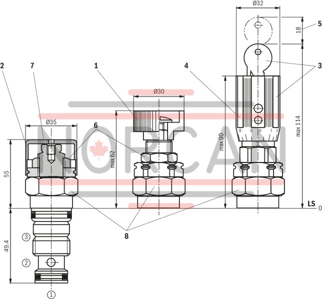
Mounting cavity, 3 main ports; M24 x 1 thread
Dimensions in mm

| 1) Depth of fit |
|
➀ |
Main port 1 (A) |
|
➁ |
Main port 2 (P), can optionally be arranged at the circumference |
|
➂ |
Main port 3 (Y), can optionally be arranged at the circumference |
|
LS |
Location shoulder |
|
1 |
Adjustment type "4" |
|
2 |
Adjustment type "5" |
|
3 |
Adjustment type "6" |
|
4 |
Adjustment type "7" |
|
5 |
Space required to remove the key |
|
6 |
Lock nut SW24 |
|
7 |
Hexagon SW10 |
|
8 |
Hexagon SW30, tightening torque for screw-in MA = 50 Nm |
|
➀ |
Main port 1 (A) |
|
➁ |
Main port 2 (P) |
|
➂ |
Main port 3 (Y) |
|
LS |
Location shoulder |