

BOSCH REXROTH
R900477396
$983.98 USD
- BOSCH REXROTH
- Material:R900477396
- Model:ZDR6DP1-4X/150YMSO43
Quantity in stock: 0
The Bosch Rexroth ZDR6DP1-4X/150YMSO43 (R900477396) is a direct-operated pressure reducing valve designed for precise control in hydraulic systems. This sandwich plate valve is integral in managing and maintaining a pre-set secondary pressure level, ensuring stability and performance in various applications. The ZDR6DP1-4X/150YMSO43 features a robust housing, a sensitive control spool, and a durable compression spring that work together to regulate pressure effectively. This model is equipped with an adjustment mechanism that allows for the fine-tuning of the secondary pressure according to system requirements. Additionally, it comes with an optional check valve for version A, which permits free flow back from channel A to A. The valve's initial position allows unobstructed flow from channel A to channel A, while any excess pressure beyond the set point activates the control spool against the spring, diverting fluid to the tank and preventing further pressure increase. In terms of versions, this model offers variety: Version A operates with internal control signal and pilot oil supply from channel A; Version P reduces pressure in channel P with internal pilot oil supply; and Version B also targets channel P but extracts pilot oil from channel B. Each version ensures that system safety is maintained by preventing excessive pressures that could lead to component damage or system failure. The ZDR6DP1-4X/150YMSO43 boasts an external leakage oil drain via bore and channel TY, as well as a pressure gauge connection for monitoring purposes. Its porting pattern conforms to ISO standards, offering flexibility for integration into various setups. Adjustment types available include rotary knob options—some with scales—and lockable versions for secure settings. Furthermore, this valve can come in a corrosion-protected design, enhancing its durability in harsh environments. With these features combined, the Bosch Rexroth ZDR6DP1-4X/150YMSO43 stands out as a reliable solution for effective pressure management in hydraulic circuits.
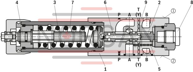
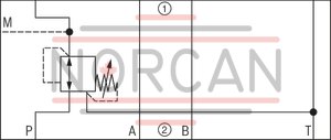
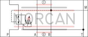
The valve type ZDR is a direct operated pressure reducing valve in sandwich plate design with pressure limitation of the secondary circuit. It is used to reduce the system pressure.
The pressure reducing valve basically comprises housing (1), control spool (2), compression spring (3), adjustment type (4) and an optional check valve.
The secondary pressure is set via the adjustment type (4).
Version "A"
The valve is open in initial position. Hydraulic fluid can flow from channel A➀ to channel A➀ without restrictions. The pressure in channel A➀ is simultaneously applied via the control line (5) at the piston area opposite the compression spring (3). If the pressure in channel A➀ exceeds the value set at the compression spring (3), the control spool (2) is pushed against the compression spring (3) to control position and keeps the set pressure in channel A➀ at a constant level.
Control signal and pilot oil are supplied internally via the control line (5) from channel A➁.
If the pressure in channel A➀ increases further due to an external force effect at the actuator, it pushes the control spool (2) even further against the compression spring (3).
In this way, channel A➀ is connected to the tank via the control edge (9) at the control spool (2) and the housing (1). So much hydraulic fluid is discharged into the tank that the pressure does not increase any further.
The leakage oil drain from the spring chamber (7) is always effected externally via the bore (6) and channel T (Y).
A pressure gauge connection (8) allows for the control of the secondary pressure at the valve.
A check valve can be used for free flow back from channel A➀ to A➀ with version “A”.
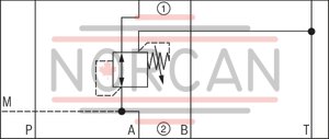
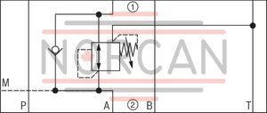
Versions “P” and “B”
For version “P”, the pressure reduction is effected in channel P➀. Control signal and pilot oil are supplied internally from channel P➀.
For version “B”, the pressure is reduced in channel P➀; but the pilot oil is extracted from channel B.
Notice:
If the directional valve is in spool position P to A, the pressure in channel B may not exceed the set secondary pressure. Otherwise, there is pressure reduction in channel A.
Type ZDR 6 DA1-4X/.YM…
|
① |
component side |
|
② |
plate side |
|
01 |
02 |
03 |
04 |
05 |
06 |
07 |
08 |
09 |
10 |
11 |
12 |
13 |
14 |
||
|
Z |
DR |
6 |
D |
– |
4X |
/ |
Y |
* |
|
01 |
Sandwich plate valve |
Z |
|
02 |
Pressure reducing valve |
DR |
|
03 |
Size 6 |
6 |
|
04 |
Direct operated |
D |
|
05 |
Pressure reduction in channel A➁ |
A |
|
Pressure reduction in channel B➁ |
B |
|
|
Pressure reduction in channel P➁ |
P |
|
|
Adjustment type |
||
|
06 |
Rotary knob |
1 |
|
Sleeve with hexagon and protective cap ("J3" version without protective cap) |
2 |
|
|
Lockable rotary knob with scale |
3 1) |
|
|
Rotary knob with scale |
7 |
|
|
07 |
Component series 40 … 49 (40 … 49: unchanged installation and mounting dimensions) |
4X |
|
08 |
Secondary pressure up to 25 bar |
25 |
|
Secondary pressure up to 75 bar |
75 |
|
|
Secondary pressure up to 150 bar |
150 |
|
|
Secondary pressure 210 bar |
210 |
|
|
Secondary pressure up to 315 bar (only version "B", "P", and "2") |
315 |
|
|
09 |
Internal pilot oil supply, external pilot oil return |
Y |
|
10 |
With check valve (only version "A") |
no code |
|
Without check valve |
M |
|
|
Corrosion resistance |
||
|
11 |
None |
no code |
|
Improved corrosion protection (240 h salt spray test according to EN ISO 9227) |
J3 |
|
|
Seal material |
||
|
12 |
NBR seals |
no code |
|
FKM seals |
V |
|
|
Observe compatibility of seals with hydraulic fluid used. |
||
|
13 |
Without locating hole |
no code |
|
With locating hole |
/60 2) |
|
|
With locating hole and locking pin ISO 8752-3x8-St |
/62 |
|
|
13 |
Further details in the plain text |
* |
| 1) | H-Key with material no. R900008158 is included in the scope of delivery. |
| 2) | Locking pin ISO 8752-3x8-St, material no. R900005694 (separate order) |
Notes:
For valve types for use in potentially explosive areas, refer to data sheet 07011. Preferred types and standard units are contained in the EPS (standard price list).general
|
Size |
6 | ||
|
Weight (approx.) |
kg |
1.2 | |
|
Installation position |
any | ||
|
Ambient temperature range |
NBR seals |
°C |
-30 … +80 |
|
FKM seal |
°C |
-20 … +80 | |
|
MTTFD values according to EN ISO 13849 1) |
Years |
150 … 1,200 | |
| 1) | For further details, see data sheet 08012 |
hydraulic
|
Size |
6 | ||
|
Maximum operating pressure (Input) |
Version "B", "P" |
bar |
350 |
|
Version "A" |
bar |
315 | |
|
Maximum secondary pressure 1) |
Outlet |
bar |
25 75 150 210 315 |
|
Maximum counter pressure |
Port T (Y) |
bar |
160 |
|
Maximum flow |
l/min |
50 | |
|
Hydraulic fluid |
see table | ||
|
Hydraulic fluid temperature range |
NBR seals |
°C |
-30 … +80 |
|
FKM seal |
°C |
-20 … +80 | |
|
Viscosity range |
mm²/s |
10 … 800 | |
|
Maximum admissible degree of contamination of the hydraulic fluid 2) |
Class 20/18/15 according to ISO 4406 (c) | ||
| 1) | 315 bar only with version “B” and “P” |
| 2) | The cleanliness classes specified for the components must be adhered to in hydraulic systems. Effective filtration prevents faults and simultaneously increases the life cycle of the components. For the selection of the filters, see www.boschrexroth.com/filter. |
|
Hydraulic fluid |
Classification |
Suitable sealing materials |
Standards |
Data sheet |
|
|
Mineral oils |
HL, HLP, HLPD |
NBR, FKM |
DIN 51524 |
90220 |
|
|
Bio-degradable 1) |
Insoluble in water |
HETG |
NBR, FKM |
ISO 15380 |
90221 |
|
HEES |
FKM |
||||
|
Soluble in water |
HEPG |
FKM |
ISO 15380 |
||
|
Flame-resistant |
Water-free |
HFDU (glycol base) |
FKM |
ISO 12922 |
90222 |
|
HFDU (ester base) 1) |
FKM |
||||
|
HFDR 1) |
FKM |
||||
|
Containing water 1) |
HFC (Fuchs Hydrotherm 46M, Petrofer Ultra Safe 620) |
NBR |
ISO 12922 |
90223 |
|
|
Important information on hydraulic fluids: For more information and data on the use of other hydraulicfluids, please refer to the data sheets above or contact us. There may be limitations regarding the technical valve data (temperature, pressure range, life cycle, maintenance intervals, etc.). The ignition temperature of the hydraulic fluid used must be 50 K higher than the maximum surface temperature. Flame-resistant - containing water: Maximum pressure differential 210 bar, otherwise, increased cavitation erosion Life cycle as compared to operation with mineral oil HL, HLP 30 … 100%. Maximum hydraulic fluid temperature 60 °C |
|||||
| 1) | In connection with the corrosion-protected version “J3”, small amounts of dissolved zinc may get into the hydraulic system. |
For applications outside these parameters, please consult us!
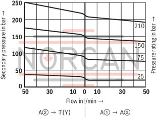
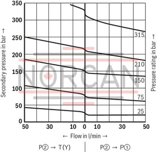
(measured with HLP46, ϑOil = 40 ±5 °C)
pA-qV characteristic curves
Version "A"
pA-qV characteristic curves
Version "B" and "P"
Δpmin-qV characteristic curves
Version "A"
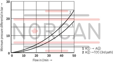
Δpmin-qV characteristic curves
Version "B" and "P"
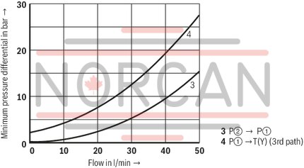
Δp-qV characteristic curves
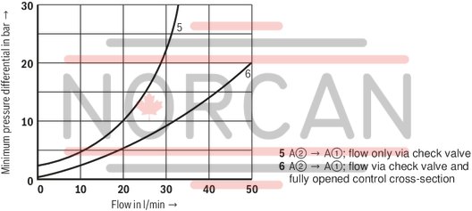
Notices:
The curve development is maintained if the pressure is set lower according to the pressure rating. The characteristic curves apply to the pressure at the valve output pT = 0 bar across the entire flow range.Version "P...YM"
Version "A...YM"
Version "B…YM"
Version "A...Y"
|
① |
component side |
|
② |
plate side |
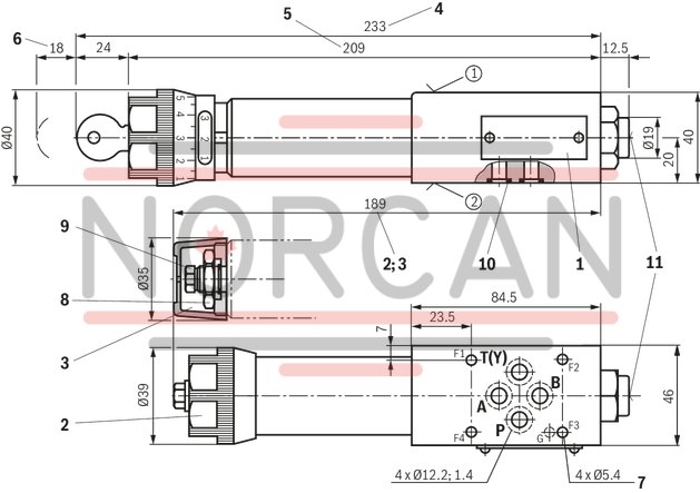
Version "A"
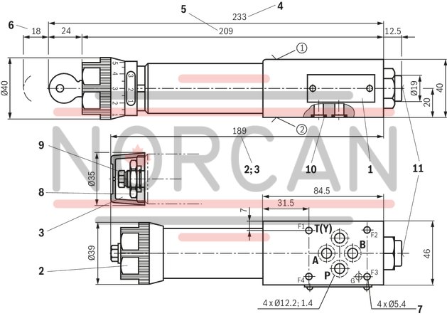
Dimensions in mm
|
|
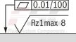
Required surface quality of the valve contact surface |
|
➀ |
component side – porting pattern according to ISO 4401-03-02-0-05 (with or without locating hole); (with locating hole Ø3 x 5 mm deep) |
|
➁ |
plate side – Porting pattern according to ISO 4401-03-02-0-05 (with or without locating hole); (with locating hole Ø3 x 5 mm deep for locking pin ISO 8752-3x8-St, material no. R900005694, separate order) |
|
1 |
Name plate |
|
2 |
Adjustment type "1" |
|
3 |
Adjustment type "2" |
|
4 |
Adjustment type "3" |
|
5 |
Adjustment type "7" |
|
6 |
Space required to remove the key |
|
7 |
Valve mounting bores |
|
8 |
Lock nut SW24 |
|
9 |
Hexagon SW10 |
|
10 |
Identical seal rings for ports A, B, P, T (Y) |
|
11 |
Pressure gauge connection G1/4; 12 mm deep; internal hexagon SW6 |
Valve mounting screw (separate order)
4 hexagon socket head cap screws ISO 4762-M5-10.9
Notices:
Length and tightening torque of the valve mounting screws must be calculated according to the components mounted under and over the sandwich plate valve. The dimensions are nominal dimensions which are subject to tolerances.Version "B" and "P"
Dimensions in mm
|
|
|
Required surface quality of the valve contact surface |
|
➀ |
component side – porting pattern according to ISO 4401-03-02-0-05 (with or without locating hole); (with locating hole Ø3 x 5 mm deep) |
|
➁ |
plate side – Porting pattern according to ISO 4401-03-02-0-05 (with or without locating hole); (with locating hole Ø3 x 5 mm deep for locking pin ISO 8752-3x8-St, material no. R900005694, separate order) |
|
1 |
Name plate |
|
2 |
Adjustment type "1" |
|
3 |
Adjustment type "2" |
|
4 |
Adjustment type "3" |
|
5 |
Adjustment type "7" |
|
6 |
Space required to remove the key |
|
7 |
Valve mounting bores |
|
8 |
Lock nut SW24 |
|
9 |
Hexagon SW10 |
|
10 |
Identical seal rings for ports A, B, P, T (Y) |
|
11 |
Pressure gauge connection G1/4; 12 mm deep; internal hexagon SW6 |
Valve mounting screw (separate order)
4 hexagon socket head cap screws ISO 4762-M5-10.9
Notices:
Length and tightening torque of the valve mounting screws must be calculated according to the components mounted under and over the sandwich plate valve. The dimensions are nominal dimensions which are subject to tolerances.|
Denomination |
Part number |
|
Protective cap |
R900135501 |