

BOSCH REXROTH
R900490267
$857.66 USD
- BOSCH REXROTH
- Material:R900490267
- Model:DR6DP2-5X/75YMJ
Quantity in stock: 0
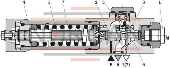
The Bosch Rexroth DR6DP2-5X/75YMJ (R900490267) is a high-performance direct operated pressure reducing valve designed for subplate mounting with porting patterns that conform to DIN form A and ISO standards, including an optional locating hole. This valve is adept at maintaining a regulated secondary circuit pressure by employing an adjustment type mechanism that allows for precise control. In its default state, the valve permits unrestricted flow from channel P to channel A, while the secondary pressure is simultaneously managed via a control line acting on a piston counterbalanced by a compression spring. When the pressure in channel A surpasses the pre-set spring value, the control spool shifts into a regulatory position to stabilize the pressure level. The design ensures internal signal and pilot oil routing through the control line from channel A. An increase in pressure due to external forces on the actuator causes further displacement of the control spool against the spring, connecting channel A to TY and allowing excess hydraulic fluid to discharge into the tank, preventing significant pressure spikes. Leakage oil from the spring chamber is consistently directed externally through channel TY. The valve also offers provisions for installing an optional check valve for unimpeded flow back from channel A to P. Monitoring of secondary pressure is facilitated by a dedicated pressure gauge connection. The DR6DP2-5X/75YMJ features various adjustment types such as a rotary knob, threaded pin with hexagon and protective cap, lockable rotary knob with scale, or rotary knob with scale for user-friendly operation. It also includes different pressure ratings and an optional check valve feature. This versatility makes it suitable for a wide range of hydraulic applications where consistent secondary pressure control is required.
The valve type DR 6 DP is a direct operated pressure reducing valve in 3-way version, i. e. with pressure limitation of the secondary circuit.
It is used to limit a system pressure. The secondary pressure is set via the adjustment type (4)
The valve is open in initial position. Hydraulic fluid can flow from channel P to channel A without restrictions. The pressure in channel A is simultaneously applied via the control line (6) at the piston area opposite the compression spring (3). If the pressure in channel A exceeds the value set at the compression spring (3), the control spool (2) moves to control position and keeps the set pressure in channel A at a constant level.
Signal and pilot oil come internally via the control line (6) from channel A.
If the pressure in channel A increases further due to an external force effect at the actuator, it pushes the control spool (2) even further against the compression spring (3).
In this way, channel A is connected to channel T(Y) via the control edge (8) at the control spool (2). So much hydraulic fluid is discharged into the tank that the pressure can only increase slightly.
The leakage oil discharge from the spring chamber (7) is always effected externally via channel T(Y).
For the free flow back from channel A to channel P, a check valve (5) can optionally be installed.
A pressure gauge connection (1) allows for the control of the secondary pressure.
Type DR 6 DP1-5X/.Y…
|
01 |
02 |
03 |
04 |
05 |
06 |
07 |
08 |
09 |
||
|
DR6DP |
– |
5X |
/ |
Y |
* |
|
01 |
Pressure reducing valve, direct operated, size 6 |
DR 6 DP |
|
Adjustment type |
||
|
02 |
Rotary knob |
1 |
|
Grub screw with hexagon and protective cap |
2 |
|
|
Lockable rotary knob with scale |
31) |
|
|
Rotary knob with scale |
7 |
|
|
03 |
Component series 50 … 59 (50 … 59: unchanged installation and connection dimensions) |
5X |
|
04 |
Maximum secondary pressure 25 bar |
25 |
|
Maximum secondary pressure 75 bar |
75 |
|
|
Maximum secondary pressure 150 bar |
150 |
|
|
Maximum secondary pressure 210 bar |
210 |
|
|
Maximum secondary pressure 315 bar |
3152) |
|
|
05 |
Internal pilot oil supply, external leakage oil discharge |
Y |
|
06 |
With check valve |
no code |
|
Without check valve |
M |
|
|
Seal material |
||
|
07 |
NBR seals |
no code |
|
FKM seals (other seals on request) Attention! Observe compatibility of seals with the hydraulic fluid used! |
V |
|
|
08 |
Without locating hole |
no code |
|
With locating hole |
/60 3) |
|
|
With locating hole and locking pin ISO 8752-3x8-St |
/62 |
|
|
09 |
Further details in the plain text |
* |
| 1) H-key with material no. R900008158 is included in the scope of delivery. | |
| 2) Only with adjustment type “2” and without check valve | |
| 3) Locking pin ISO 8752-3x8-St, material no. R900005694 (separate order) |
Preferred types and standard units are contained in the EPS (standard price list).
general
|
Size |
6 | ||
|
Installation position |
any | ||
|
Storage temperature range |
NBR seals |
°C |
-30 ... +80 |
|
FKM seals |
°C |
-20 ... +80 | |
|
Weight |
kg |
1.2 | |
hydraulic
|
Size |
6 | ||
|
Maximum operating pressure |
Port P |
bar |
315 |
|
Maximum secondary pressure |
Anschluss A |
bar |
25 75 150 210 315 |
|
Maximum counter pressure |
Port T (Y) |
bar |
160 |
|
Maximum flow |
l/min |
60 | |
|
Hydraulic fluid |
see table | ||
|
Hydraulic fluid temperature range |
NBR seals |
°C |
-30 … +80 |
|
FKM seal |
°C |
-20 … +80 | |
|
Viscosity range |
mm²/s |
10 … 800 | |
|
Maximum admissible degree of contamination of the hydraulic fluid 1) |
Class 20/18/15 according to ISO 4406 (c) | ||
| 1) | The cleanliness classes specified for the components must be adhered to in hydraulic systems. Effective filtration prevents faults and simultaneously increases the life cycle of the components. For the selection of the filters, see www.boschrexroth.com/filter. |
|
Hydraulic fluid |
Classification |
Suitable sealing materials |
Standards |
|
|
Mineral oils and related hydrocarbons |
HL, HLP, HLPD |
NBR, FKM |
DIN 51524 |
|
|
Environmentally compatible |
Insoluble in water |
HETG |
NBR, FKM |
ISO 15380 |
|
HEES |
FKM |
|||
|
Soluble in water |
HEPG |
FKM |
ISO 15380 |
|
|
Containing water |
Water-free |
HFDU, HFDR |
FKM |
ISO 12922 |
|
Containing water |
HFC (Fuchs Hydrotherm 46M, Petrofer Ultra Safe 620) |
NBR |
ISO 12922 |
|
|
Important information on hydraulic fluids! For further information and data on the use of other hydraulic fluids, please refer to data sheet 90220 or contact us! There may be limitations regarding the technical valve data (temperature, pressure range, life cycle, maintenance intervals, etc.)!Flame-resistant – containing water: Maximum operating pressure 210 bar Maximum hydraulic fluid temperature 60 °C Expected life cycle as compared to HLP hydraulic oil 30 % to 100 % |
||||
For applications outside these parameters, please consult us!
(measured with HLP46, ϑOil = 40 ±5 °C)
pA-qV characteristic curves
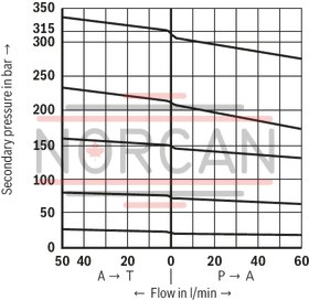
pA-qV characteristic curves
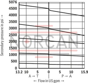
Notice!
The curve development is maintained if the pressure is set lower according to the pressure rating.
The characteristic curves apply to the pressure at the valve output p = 0 bar across the entire flow range.
Δp-qV characteristic curves
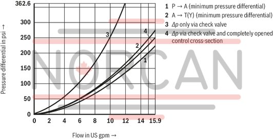
Δp-qV characteristic curves
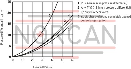
|
1 |
P to A (minimum pressure differential) |
|
2 |
A to T(Y) (minimum pressure differential) |
|
3 |
Δp only via check valve |
|
4 |
Δp via check valve and fully opened control cross-section |
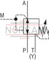
Version "M"
Without check valve
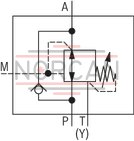
Version "no code"
With check valve
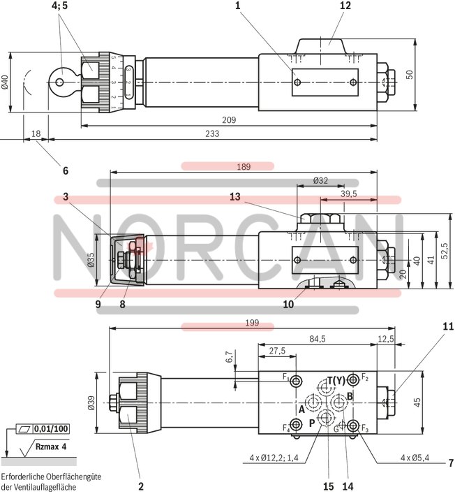
Dimensions in mm
Dimensions in mm
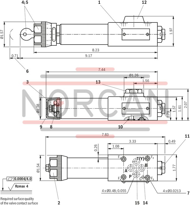
|
1 |
Name plate |
|
2 |
Adjustment type "1" |
|
3 |
Adjustment type "2" |
|
4 |
Adjustment type "3" |
|
5 |
Adjustment type "7" |
|
6 |
Space required to remove the key |
|
7 |
Valve mounting bores |
|
8 |
Lock nut SW24 |
|
9 |
Hexagon SW10 |
|
10 |
Identical seal rings for ports A, B, P, T (Y) |
|
11 |
Pressure gauge connection G1/4; 12 mm deep; internal hexagon SW6 |
|
12 |
Without check valve |
|
13 |
With check valve |
|
14 |
Port B without function |
|
15 |
Porting pattern according toISO 4401-03-02-0-05 (with locating hole for locking pin ISO 8752-3x8-St, material no. R900005694, separate order) |
Subplates (separate order)
(without locating hole)
G 341/01 (G1/4)
G 342/01 (G3/8)
G 502/01 (G1/2)
(with locating hole)
G 341/60 (G1/4)
G 342/60 (G3/8)
G 502/60 (G1/2)
Valve mounting screws (separate order)
4 metric hexagon socket head cap screws
ISO 4762 - M5 x 50 - 10.9-flZn-240h-L
at friction coefficient μtotal = 0.09 to 0.14,
tightening torque MA = 7 Nm] ± 10% ,
material no. R913000064
4 hexagon socket head cap screws UNC
10-24 UNC x 2” (on request)