


BOSCH REXROTH
R900516283
- BOSCH REXROTH
- Material:R900516283
- Model:LC100A40E6X/-104
Quantity in stock: 0
The Bosch Rexroth LC100A40E6X/-104 (R900516283) is a sophisticated hydraulic way cartridge valve designed for integration into a compact block design. This valve is an essential component for systems requiring precise control over pressure, directional, and throttle functions. The LC100A40E6X/-104 can be utilized in various applications due to its ability to be controlled by pilot control valves, which allows for the implementation of multiple functions within a single unit, enhancing cost-effectiveness and system efficiency. The construction of this model includes a control cover that houses the control bores and may include additional features such as stroke limitation, hydraulically controlled directional seat valves, or shuttle valves tailored to the specific needs of the application. For further customization, electrically operated directional spool or seat valves can be attached to the control cover. The installation kit comprises several components including a bushing, ring (applicable up to certain sizes), valve poppet with optional damping nose configurations, and a closing spring. The functionality of the LC100A40E6X/-104 is pressure-dependent, with three critical pressurized areas designated as A1, A2, and A3. These areas interact to determine the spool position through their respective forces in either the opening or closing direction of the valve. The valve allows flow from A to B or vice versa and ensures that pressurization of area A3 effectively blocks channel A without leakage when pilot oil is discharged from channel B or supplied externally. This Bosch Rexroth way cartridge valve stands out due to its variable area ratios which influence cracking pressures and flow characteristics. As such, it's suitable for applications where precise hydraulic flow control is paramount. The LC100A40E6X/-104 exemplifies Bosch Rexroth's commitment to engineering excellence by offering reliable performance in fluid power systems where space-saving installation and multifunctional capabilities are required.
2-way cartridge valves are elements that have been designed for a compact block design. The power section with connections A and B is installed into the control block in a receiving hole standardized according to ISO 7368 and closed with a cover. In most cases, the cover is also the connection from the control side of the power section to the pilot control valves.
By control with respective pilot control valves, the power section can be applied for pressure, directional and throttle functions or a combination of these functions. Particularly efficient solutions are realized by adjustment of the size to various flows of the individual ways of an actuator. The application of power sections of elements for multiple functions is very cost-effective.
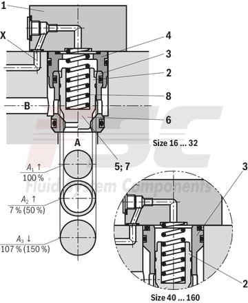
2-way cartridge valves generally consist of control cover (1) and installation kit (2). The control cover contains the control bores and optionally a stroke limitation function, a hydraulically controlled directional seat valve or a shuttle valve according to the required overall function. Additionally, electrically operated directional spool or seat valves can be installed at a control cover. The installation kit consists of a bushing (3), ring (4) (only up to NG32), valve poppet (5), optionally with damping nose (6) or without damping nose (7) as well as closing spring (8).
The function of 2-way cartridge valves is pressure-dependent. This way, three crucial pressurized areas are realized for the function. A1, A2, A3. The area at valve seat A1 is observed as 100 %. Depending on the version, the annulus area A2 realized by grading is 7 % or 50 % of area A1. The area ratio A1 : A2 is respectively either 14.3 : 1 or 2 : 1. The area A3 is identical to the sum of areas A1 + A2. Due to the different area ratios A1 : A2 and the resulting different annulus areas (A2), the area A3 is one time 107 % and another time 150 % of the area A1 at the seat, which is observed as 100 %.
In general, the following applies:
The areas A1 and A2 are effective in opening direction. The area A3 and the spring are effective in closing direction. The direction of action of the resulting force from the opening and closing forces determines the spool position of the 2-way cartridge valve.
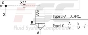
The 2-way cartridge valves can be passed from A to B or from B to A. Pressurization of area A3 by pilot oil discharge from channel B or external pilot oil supply, channel A is blocked without leakage.
|
01 |
02 |
03 |
04 |
05 |
06 |
07 |
|
|
LC |
/ |
|
Type |
||
|
01 |
Cartridge valve |
LC |
|
Size |
||
|
02 |
Size 16 |
16 |
|
Size 25 |
25 |
|
|
Size 32 |
32 |
|
|
Size 40 |
40 |
|
|
Size 50 |
50 |
|
|
Size 63 |
63 |
|
|
Size 80 |
80 |
|
|
Size 100 |
100 |
|
|
Size 125 |
125 |
|
|
Size 160 |
160 |
|
|
Spool design 1) |
||
|
03 |
A1 : A2 = 2 : 1 (A2 = 50 %) |
A |
|
A1 : A2 = 14.3 : 1 (A2 = 7 %) |
B |
|
|
Cracking pressure |
||
|
04 |
0 bar (without spring) |
00 |
|
approx. 0.5 bar |
05 |
|
|
approx. 1 bar |
10 |
|
|
approx. 2 bar |
20 |
|
|
approx. 3 bar (NG125 only) |
30 |
|
|
approx. 4 bar (not NG125) |
40 |
|
|
Damping |
||
|
05 |
Valve poppet without damping nose |
E |
|
Valve poppet with damping nose |
D |
|
|
Component series |
||
|
06 |
Component series 70 ... 79 (70 ... 79: unchanged installation and connection dimensions) 2) |
7X |
|
Component series 60 … 69 (60 … 69: unchanged installation and connection dimensions) 3) |
6X |
|
|
Component series 20 ... 29 (20 ... 29: unchanged installation and connection dimensions) 4) |
2X |
|
|
Seal material |
||
|
07 |
NBR seals |
no code |
|
FKM seals |
V |
|
|
Observe compatibility of seals with hydraulic fluid used. (Other seals upon request) |
||
| 1) | See "Product description" |
| 2) | Size 16 ... 63 |
| 3) | Size 80 ... 100 |
| 4) | Size 125 ... 160 |
general
|
Size |
16 | 25 | 32 | 40 | 50 | 63 | 80 | 100 | 125 | 160 | ||
|
Weight |
kg |
0.25 | 0.5 | 1.1 | 1.9 | 3.9 | 7.2 | 13 | 27 | 44 | 75 | |
|
Ambient temperature range |
NBR seals |
°C |
-30 … +60 | |||||||||
|
FKM seals |
°C |
-20 … +60 | ||||||||||
|
MTTFD values according to EN ISO 13849 1) |
Years |
150 | ||||||||||
| 1) | For further details, see data sheet 08012 |
hydraulic
|
Size |
16 | 25 | 32 | 40 | 50 | 63 | 80 | 100 | 125 | 160 | ||
|
Maximum operating pressure 1) |
Port A |
bar |
315 350 420 |
|||||||||
|
Port B |
bar |
315 350 420 |
||||||||||
|
Maximum flow 2) |
l/min |
25000 | ||||||||||
|
Hydraulic fluid |
see table "Hydraulic fluid" | |||||||||||
|
Hydraulic fluid temperature range |
NBR seals |
°C |
-30 … +80 | |||||||||
|
FKM seals |
°C |
-20 … +80 | ||||||||||
|
Viscosity range |
mm²/s |
2.8 … 500 | ||||||||||
|
Maximum admissible degree of contamination of the hydraulic fluid, cleanliness class according to ISO 4406 (c) 3) |
Class 20/18/15 | |||||||||||
| 1) | dependent on the attached directional valve |
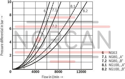
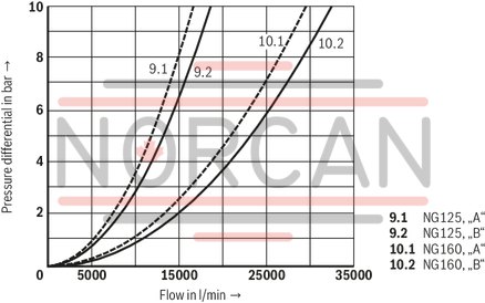
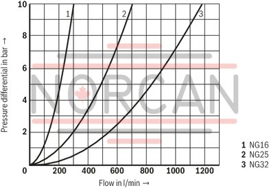
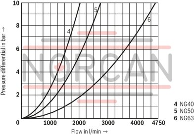
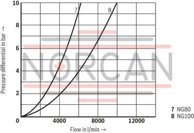
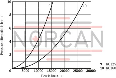
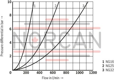
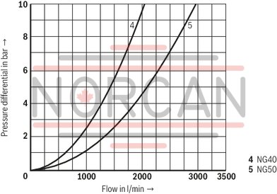
| 2) | NG-dependent; see characteristic curves |
| 3) | The cleanliness classes specified for the components must be adhered to in hydraulic systems. Effective filtration prevents faults and simultaneously increases the life cycle of the components. For the selection of the filters, see www.boschrexroth.com/filter. |
|
Hydraulic fluid |
Classification |
Suitable sealing materials |
Standards |
Data sheet |
|
|
Mineral oils |
HL, HLP, HLPD, HVLP, HVLPD |
NBR, FKM |
DIN 51524 |
90220 |
|
|
Bio-degradable 1) |
Insoluble in water |
HETG |
NBR, FKM |
ISO 15380 |
90221 |
|
HEES |
FKM |
||||
|
Soluble in water |
HEPG |
FKM |
ISO 15380 |
||
|
Flame-resistant |
Water-free |
HFDU (glycol base) |
FKM |
ISO 12922 |
90222 |
|
HFDU (ester base) 1) |
FKM |
||||
|
Containing water 1) |
HFC (Fuchs Hydrotherm 46M, Petrofer Ultra Safe 620) |
NBR |
ISO 12922 |
90223 |
|
|
Important information on hydraulic fluids: For more information and data on the use of other hydraulicfluids, please refer to the data sheets above or contact us. There may be limitations regarding the technical valve data (temperature, pressure range, life cycle, maintenance intervals, etc.). Flame-resistant - containing water: Life cycle as compared to operation with mineral oil HL, HLP 30 … 100%. Maximum hydraulic fluid temperature 60 °C Bio-degradable and flame-resistant: If this hydraulic fluid is used, small amounts of dissolved zinc may get into the hydraulic system. |
|||||
| 1) | Not recommended for corrosion-protected version "J3" (contains zinc) |
Size of the annulus area
|
Surface in cm2 |
Version |
Size |
|||||||||
|
16 |
25 |
32 |
40 |
50 |
63 |
80 |
100 |
125 |
160 |
||
|
A1 |
LC..A.. |
1,89 |
4,26 |
6,79 |
11,1 |
19,63 |
30,02 |
37,9 |
63,6 |
95 |
160,6 |
|
LC..B.. |
2,66 |
5,73 |
9,51 |
15,55 |
26,42 |
41,28 |
52,8 |
89,1 |
133,7 |
224,8 |
|
|
A2 |
LC..A.. |
0,95 |
1,89 |
3,39 |
5,52 |
8,64 |
14,0 |
18,84 |
31,4 |
48 |
79,9 |
|
LC..B.. |
0,18 |
0,43 |
0,67 |
1,07 |
1,85 |
2,90 |
3,94 |
5,9 |
9,3 |
15,7 |
|
|
A3 |
LC..A.. |
2,84 |
6,16 |
10,18 |
16,62 |
28,27 |
44,2 |
56,74 |
95 |
143 |
240,5 |
|
LC..B.. |
2,84 |
6,16 |
10,18 |
16,62 |
28,27 |
44,2 |
56,74 |
95 |
143 |
240,5 |
|
Spool form (damping nose)
|
Version |
Size |
|||||||||||
|
16 |
25 |
32 |
40 |
50 |
63 |
80 |
100 |
125 |
160 |
|||
|
Stroke |
cm |
LC..E.. |
0,9 |
1,17 |
1,4 |
1,7 |
2,1 |
2,3 |
2,4 |
3,0 |
3,8 |
5,0 |
|
LC..D.. |
0,9 |
1,17 |
1,4 |
1,9 |
2,3 |
2,8 |
3,0 |
3,8 |
4,8 |
6,5 |
||
|
Pilot volume |
cm3 |
LC..E.. |
2,56 |
7,21 |
14,3 |
28,3 |
59,4 |
102 |
136 |
285 |
544 |
1203 |
|
LC..D.. |
2,56 |
7,21 |
14,3 |
31,6 |
65,0 |
124 |
170 |
361 |
687 |
1563 |
||
|
Theoretical pilot flow 1) |
l/min |
LC..E.. |
15,4 |
43,3 |
86 |
170 |
356 |
612 |
816 |
1710 |
3264 |
7218 |
|
LC..D.. |
15,4 |
43,3 |
86 |
190 |
390 |
744 |
1020 |
2166 |
4122 |
9378 |
||
| 1) | Theoretical pilot flow for realization of a switching time of 10 ms |
Notice:
Spools with damping nose are mainly used in applications with stroke limitation and spool position monitoring. Due to the better flow values, we recommend the spool without damping nose by default.
Cracking pressure in bar
|
Version |
Size |
||||||||||
|
16 |
25 |
32 |
40 |
50 |
63 |
80 |
100 |
125 |
160 |
||
|
Direction of flow A to B |
LC..A 00.. |
0,02 |
0,025 |
0,05 |
0,05 |
0,05 |
0,07 |
0,07 |
0,1 |
0,15 |
0,15 |
|
LC..A 05.. |
0,35 |
0,35 |
0,36 |
0,35 |
0,37 |
0,31 |
0,44 |
0,43 |
0,43 |
0,45 |
|
|
LC..A 10.. |
0,70 |
0,68 |
0,72 |
0,71 |
0,67 |
0,64 |
0,88 |
0,88 |
0,88 |
– |
|
|
LC..A 20.. |
2,03 |
2,18 |
2,12 |
2,02 |
2,01 |
2,0 |
1,75 |
1,75 |
1,76 |
1,94 |
|
|
LC..A 30.. |
– |
– |
– |
– |
– |
– |
– |
– |
2,05 |
– |
|
|
LC..A 40.. |
3,50 |
3,90 |
3,80 |
4 |
4,11 |
3,8 |
3,13 |
3,04 |
– |
4,42 |
|
|
LC..B 00.. |
0,014 |
0,02 |
0,035 |
0,035 |
0,035 |
0,05 |
0,05 |
0,07 |
0,1 |
0,1 |
|
|
LC..B 05.. |
0,25 |
0,26 |
0,26 |
0,25 |
0,28 |
0,23 |
0,31 |
0,31 |
0,31 |
0,32 |
|
|
LC..B 10.. |
0,49 |
0,50 |
0,51 |
0,51 |
0,48 |
0,47 |
0,63 |
0,63 |
0,62 |
– |
|
|
LC..B 20.. |
1,44 |
1,62 |
1,52 |
1,44 |
1,5 |
1,5 |
1,26 |
1,25 |
1,25 |
1,4 |
|
|
LC..B 30.. |
– |
– |
– |
– |
– |
– |
– |
– |
1,45 |
– |
|
|
LC..B 40.. |
2,48 |
2,90 |
2,70 |
2,86 |
3,05 |
2,8 |
2,25 |
2,17 |
– |
3,35 |
|
|
Direction of flow B to A |
LC..A 00.. |
0,04 |
0,05 |
0,1 |
0,1 |
0,1 |
0,14 |
0,14 |
0,2 |
0,30 |
0,33 |
|
LC..A 05.. |
0,69 |
0,78 |
0,72 |
0,7 |
0,84 |
0,68 |
0,88 |
0,88 |
0,86 |
0,91 |
|
|
LC..A 10.. |
1,38 |
1,53 |
1,42 |
1,43 |
1,47 |
1,37 |
1,77 |
1,78 |
1,73 |
– |
|
|
LC..A 20.. |
4,05 |
4,91 |
4,25 |
4,06 |
4,57 |
4,33 |
3,53 |
3,54 |
3,50 |
3,9 |
|
|
LC..A 30.. |
– |
– |
– |
– |
– |
– |
– |
– |
4,0 |
– |
|
|
LC..A 40.. |
6,96 |
8,74 |
7,6 |
8,05 |
9,34 |
8,15 |
6,3 |
6,2 |
– |
8,76 |
|
|
LC..B 00.. |
0,24 |
0,25 |
0,5 |
0,5 |
0,5 |
0,8 |
0,7 |
1,0 |
1,5 |
1,5 |
|
|
LC..B 05.. |
3,69 |
3,40 |
3,64 |
3,64 |
3,95 |
3,27 |
4,2 |
4,6 |
4,4 |
4,6 |
|
|
LC..B 10.. |
7,43 |
6,69 |
7,24 |
7,37 |
6,88 |
6,62 |
8,4 |
9,4 |
8,9 |
– |
|
|
LC..B 20.. |
21,3 |
21,5 |
21,6 |
20,9 |
21,4 |
20,9 |
16,9 |
18,7 |
17,9 |
20 |
|
|
LC..B 30.. |
– |
– |
– |
– |
– |
– |
– |
– |
20,7 |
– |
|
|
LC..B 40.. |
36,6 |
38,3 |
38,6 |
41,5 |
43,6 |
39,4 |
30,2 |
32,5 |
– |
44,7 |
|
For applications outside these parameters, please consult us!
(simulated with HLP46, ϑoil = 40±5 °C)
Without damping nose "E", A → B
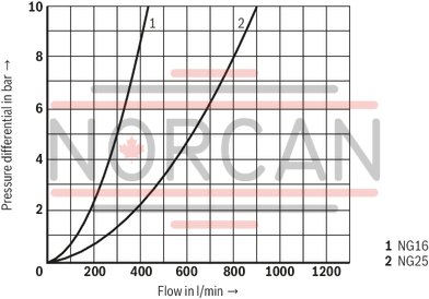
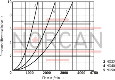
Without damping nose "E", B → A
With damping nose “D”, A → B
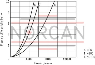
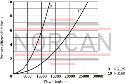
With damping nose "D", B → A
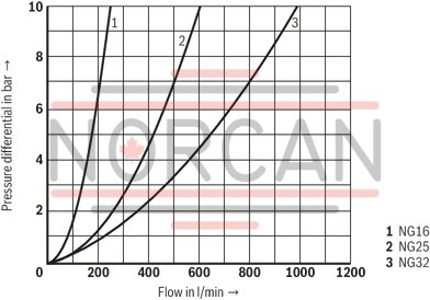
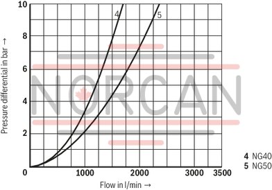
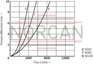
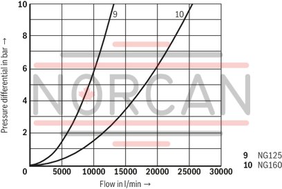
Notice:
The specified characteristic curves were simulated with 100% spool stroke and an aligned socket (see sketch under recommended socket alignment). The simulation results were validated by measurement results. The basis was an installation geometry with ØD3* (see installation under dimensions) and a simulation model according to ISO 4411/2008-10-01.
Recommended socket alignment:
Size 16...32
Bore on bore

Size 40 ... 160
Bar on bore

|
Version "E" |
Version “D” |
||

|

|

|

|
|
Area ratio A1 : A2 = 2 : 1 Version "…A.E…" |
Area ratio A1 : A2 = 14,3 : 1 Version "…B.E…" |
Area ratio A1 : A2 = 2 : 1 Version "…A.D…" |
Area ratio A1 : A2 = 14,3 : 1 Version "…B.D…" |
Additional functions with special numbers see "Information".
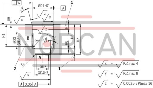
Installation bore according to ISO 7368
Dimensions in mm
|
1 |
Depth of fit |
|
2 |
Port B may be positioned around the central axis of port A. However, it must be observed that the mounting bores and the control bores are not damaged. |
|
NG |
16 | 25 | 32 | 40 | 50 | 63 | 80 | 100 | 125 | 160 | |
|
ØD1H7 |
mm |
32 | 45 | 60 | 75 | 90 | 120 | 145 | 180 | 225 | 300 |
|
ØD2 |
mm |
16 | 25 | 32 | 40 | 50 | 63 | 80 | 100 | 150 1) | 200 1) |
|
ØD3 |
mm |
16 | 25 | 32 | 40 | 50 | 63 | 80 | 100 | 125 | 160 |
|
(ØD3*) 2) |
mm |
25 | 32 | 40 | 50 | 63 | 80 | 100 | 125 | 160 | 250 |
|
ØD4H7 |
mm |
25 | 34 | 45 | 55 | 68 | 90 | 110 | 135 | 200 | 270 |
|
H1 |
mm |
42.5 | 57 | 68.5 | 84.5 | 97.5 | 127 | 170.5 | 205.5 | 255 | 368 |
|
H2 |
mm |
56 | 72 | 85 | 105 | 122 | 155 | 205 | 245 | 300 | 425 |
|
mm |
+ 0.1 | + 0.1 | + 0.1 | + 0.1 | + 0.1 | + 0.1 | + 0.1 | + 0.1 | + 0.15 | + 0.15 | |
|
H3 |
mm |
43 | 58 | 70 | 87 | 100 | 130 | 175 | 210 | 257 | 370 |
|
mm |
+ 0.2 | + 0.2 | + 0.2 | + 0.3 | + 0.3 | + 0.3 | + 0.4 | + 0.4 | + 0.5 | + 0.5 | |
|
H5 |
mm |
11 | 12 | 13 | 15 | 17 | 20 | 25 | 29 | 31 | 45 |
|
H6 |
mm |
2 | 2.5 | 2.5 | 3 | 3 | 4 | 5 | 5 | 7 | 8 |
|
mm |
- | - | - | - | - | - | - | - | ± 0.5 | ± 0.5 | |
|
H7 |
mm |
20 | 30 | 30 | 30 | 35 | 40 | 40 | 50 | 40 | 50 |
|
H8 |
mm |
2 | 2.5 | 2.5 | 3 | 4 | 4 | 5 | 5 | 5.5 | 5.5 |
|
mm |
- | - | - | - | - | - | - | - | ± 0.2 | ± 0.2 | |
|
W |
mm |
0.05 | 0.05 | 0.1 | 0.1 | 0.1 | 0.1 | 0.1 | 0.1 | 0.1 | 0.1 |
|
Ro 1) |
mm |
2 | 2 | 2 | 4 | 4 | 4 | 4 | 4 | 4 | 6.3 |
|
Ru 1) |
mm |
1 | 1 | 1 | 1 | 1 | 1 | 1 | 1 | 1 | 1 |
| 1) | Maximum dimension |
| 2) | Due to the use of a bore with ØD3*, port B protrudes over the upper limit of the area intended in ISO 7368. This is, however, possible due to the sealing concept and reduces the pressure loss during flow through the valve. Thus, we recommend a bore with ØD3*. |
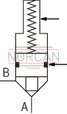
Additional functions with special numbers (upon request)
|
Symbol |
Type (examples) |
Size |
Description / special characteristic |
|
LC . A..D7X/-004 |
16 ... 50 |
With piston sealing (leakage-free) Larger spring installation space Special cover or intermediate cover "D19" required NG16 … 40: only with cracking pressure approx. 4 bar NG50 and 63: cracking pressure approx. 2 bar or higher; alternatively "without spring" |
|
LC . A..E7X/-004 |
16 ... 50 |
||
|
LC . B..E7X/-004 |
16 ... 63 |
||

|
LC . A..D6X/-104 |
80, 100 |
With piston sealing (leakage-free) as SO-004, however, no special cover required |
|
LC . A..E6X/-104 |
80, 100 |
||
|
LC . B..E6X/-104 |
80, 100 |
||
|
LC . A..D7X/-104 |
40 … 63 |
||
|
LC . A..E7X/-104 |
40 … 63 |
||
|
LC . A..E2X/-104 |
125, 160 |
||

|
LC . A05D6X/-054 |
16 |
Pulling logic with open zero position Special cover (e.g. "D54") required |
|
LC . A20D6X/-054 |
25 ... 32 |
||
|
LC . A05E6X/-054 |
16 |
||
|
LC . A..E6X/-054 |
25 ... 80 |
||
|
LC ./100 A20E6X/-054 |
32, 100 |
||
|
LC . B05E6X/-054 |
12 |
||
|
LC . B20E6X/-054 |
25 |
||
|
LC . A20D7X/-054 |
50 |
||
|
LC . A40D7X/-054 |
63 |
||
|
LC . A20E7X/-054 |
50 |
||
|
LC . A..E7X/-054 |
63 |
||

|
LC …7X/-135 |
16 … 40 |
Larger spool clearance |
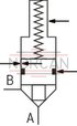
|
LC …7X/-146 |
16 … 40 |
Larger spool clearance With piston sealing (leakage-free) Larger spring installation space Special cover or intermediate cover "D19" required |

|
LC . A..D7X/-R10 |
16 |
As standard, however, larger bushing outer diameter D1 and D4 1 mm |
|
LC . A20D7X/-R10 |
25 |
||
|
LC 1. A40E7X/-R10 |
16, 32 |
||
|
LC . A..E7X/-R10 |
25, 63 |
||
|
LC . A10E7X/-R10 |
40 |
||
|
LC . A05E7X/-R10 |
50 |
||
|
LC . B..D7X/-R10 |
25 |
||
|
LC . B10D7X/-R10 |
32 |
||
|
LC . B40E7X/-R10 |
25, 40 |
||
|
LC . B..E7X/-R10 |
50, 63 |
||
|
|
LC . A..D7X/-R20 |
16 |
As standard, however, larger bushing outer diameter D1 and D4 2 mm |
|
LC . A20D7X/-R20 |
25 |
||
|
LC 1. A40E7X/-R20 |
16, 32 |
||
|
LC . A..E7X/-R20 |
25, 63 |
||
|
LC . A10E7X/-R20 |
40 |
||
|
LC . A05E7X/-R20 |
50 |
||
|
LC . B..D7X/-R20 |
25 |
||
|
LC . B10D7X/-R20 |
32 |
||
|
LC . B40E7X/-R20 |
25, 40 |
||
|
LC . B..E7X/-R20 |
50, 63 |
||

|
LC . XAB00E-7X/ |
16 … 63 |
Blind element without spool Channel A - B connected For use with available LFA cover or in connection with a cover "LFA . D-7X/FX99" |

|
LC . XAF00E-7X/ |
16 … 63 |
Blind element without spool Channel A - F connected Channel B closed For use with available LFA cover or in connection with a cover "LFA . D-7X/FX99" |

|
LC . X00E-7X/ |
16 … 63 |
Blind element without spool All channels blocked For use with available LFA cover or in connection with a cover "LFA . D-7X/FX99" |