

BOSCH REXROTH
R900572182
$332.94 USD
- BOSCH REXROTH
- Material:R900572182
- Model:2FRM6K2-1X/32QRV
Quantity in stock: 0
The Bosch Rexroth 2FRM 6 K2-1X/32QRV (R900572182) is a highly efficient screw-in cartridge valve designed for hydraulic applications requiring precise flow control and pressure compensation. This 3-way flow regulator is part of the FRM.K product family, characterized by its ability to maintain a stable flow regardless of pressure and temperature variations. The valve features a maximum operating pressure of 315 bar (4568 psi) and can handle a maximum flow rate of up to 40 l/min (10.6 gpm), making it suitable for a wide range of hydraulic systems. Equipped with an internal hexagon grub screw for adjustment, the valve allows for easy setting of the desired throttle cross-section between its components, ensuring optimal performance. The integrated pressure compensator works in conjunction with the throttling point to provide consistent flow regulation within the hydraulic circuit. Furthermore, this model includes a reverse flow check, allowing free return flow from channel B to channel A via the check valve. The Bosch Rexroth 2FRM 6 K2-1X/32QRV valve is designed with FKM sealing material, ensuring durability and resistance to various hydraulic fluids such as HL, HLP, HEES, and HEPG. Its pilot-operated spool type ensures reliability in operation, while its normally open normal position maintains system readiness. With its robust construction and meticulous design for precise control, this valve is an essential component for systems requiring dependable flow regulation under varying conditions.
2-way flow control valve
Unpacked Weight: 0.19 kg
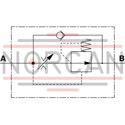
The valve type 2FRM.K2 is a 2-way flow control valve for block design installation. It is used for pressure and temperature-independent flow stabilization.
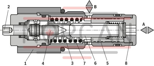
The valve basically consists of housing (1), adjustment type (2), throttling point (3), throttle bolt (4), pressure compensator (5) and check valve (6).
The flow from channel A to channel B is throttled at the throttling point (3). The throttle cross-section is set by rotation of the adjustment type (2) between the throttling point (3) and the throttle bolt (4).
For pressure-independent flow stabilization in channel B, a pressure compensator (5) is connected downstream to the throttling point (3).
The pressure compensator (5) is pressed by the compression spring (7) against the plug screw (8) and remains in open position if there is no flow through the valve. When there is a flow through the valve, the pressure in channel A applies a force on the pressure compensator (5). It is set to control position until the forces are balanced. If the pressure in channel A rises, the pressure compensator (5) moves in closing direction until the forces are balanced again. Due to this continuous compensation of the pressure compensator, a constant flow is obtained.
The free return flow from channel B to channel A is directed via the check valve (6).
| Screw-in cartridge valve |
| Maximum operating pressure 315 bar (4568 psi) |
| Maximum flow 32 l/min (8,5 gpm) |
| Cavity M22x1,5 |
| Data Sheet | Download Data Sheet |
| Max. pressure | 315 |
| Adjustment options | Grub screw with internal hexagon |
| Product family classification | Flow regulator 2 ways, pressure compensated with reverse flow check |
| Productgroup ID | 9,10,11,12,13,14 |
| Ports number | 2 |
| Sealing material | FKM |
| Cavity | M22x1,5 |
| Product type | 2FRM.K |
| Max. flow | 32 |
| Type of connection | Screw-in cartridge valve |
| Normal position | Normally open |
| Nominal flow | 32 |
| Direct - Pilot | Pilot operated |
| Product family | Flow regulator |
| Spool Poppet | Spool type |
| Weight | 0.19 |
| Hydraulic fluid | HL,HLP,HEES,HEPG |
|
01 |
02 |
03 |
04 |
05 |
06 |
07 |
08 |
09 |
||
|
2FRM |
K |
2 |
– |
1X |
/ |
R |
V |
* |
|
01 |
2-way flow control valve |
2FRM |
|
02 |
Size 6 |
6 |
|
Size 10 |
10 |
|
|
03 |
Cartridge valve |
K |
|
Adjustment type |
||
|
04 |
Internal hexagon |
2 |
|
05 |
Component series 10 ... 19 (10 ... 19: unchanged installation and connection dimensions) |
1X |
|
Flow (A → B) |
||
|
06 |
up to 6.0 l/min (size 6) |
6Q |
|
up to 32.0 l/min (size 6) |
32Q |
|
|
up to 60.0 l/min (size 10) |
60Q |
|
|
07 |
With check valve |
R |
|
Seal material |
||
|
08 |
FKM seals (other seals upon request) |
V |
|
Observe compatibility of seals with hydraulic fluid used. (Other seals upon request) |
||
|
09 |
Further details in the plain text |
|
Preferred types and standard units are contained in the EPS (standard price list).
general
|
Size |
6 | 10 | |
|
Weight |
kg |
0.19 | 0.6 |
|
Installation position |
any | ||
|
Ambient temperature |
°C |
-20 … +50 | |
hydraulic
|
Size |
6 | 10 | |||
|
Maximum operating pressure |
Anschluss A |
bar |
315 | 210 | |
|
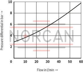
Pressure differential Δp with free return flow B → A |
See characteristic curves | ||||
|
Minimum pressure differential |
bar |
18 | |||
|
Pressure stable (qV max) up to Δp = 315 bar / 210 bar |
% |
± 3 | |||
|
Flow |
Pv max |
l/min |
6 | 32 | 60 |
|
Pv min |
l/min |
0.05 | 0.25 | 0.5 | |
|
Hydraulic fluid |
see table | ||||
|
Hydraulic fluid temperature range |
°C |
-20 … +80 | |||
|
Viscosity range |
mm²/s |
10 … 800 | |||
|
Maximum admissible degree of contamination of the hydraulic fluid 1) |
Class 20/18/15 according to ISO 4406 (c) | ||||
| 1) | The cleanliness classes specified for the components must be adhered to in hydraulic systems. Effective filtration prevents faults and simultaneously increases the life cycle of the components. For the selection of the filters, see www.boschrexroth.com/filter. |
|
Hydraulic fluid |
Classification |
Suitable sealing materials |
Standards |
|
|
Mineral oil |
HL, HLP |
FKM, NBR |
DIN 51524 |
|
|
Bio-degradable |
Insoluble in water |
HEES (synthetic esters) |
FKM |
VDMA 24568 |
|
HETG (rape seed oil) |
FKM, NBR |
|||
|
Soluble in water |
HEPG (polyglycols) |
FKM |
VDMA 24568 |
|
|
Other hydraulic fluids on request |
||||
For applications outside these parameters, please consult us!
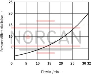
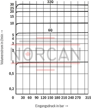
(measured with HLP46, ϑOil = 40 ±5 °C)
Size 6
Δp-qV characteristic curve via check valve (B → A) orifice closed
Size 6
Flow qV depending on inlet pressure p
Size 10
Δp-qV characteristic curve via check valve (B → A) orifice closed
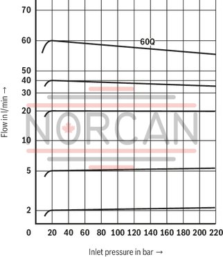
Size 10
Flow qV depending on inlet pressure p
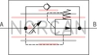
Detailed
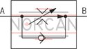
simple
|
NG |
L1 |
L2 |
L3 |
L4 |
ØD1 |
|
mm |
mm |
mm |
mm |
mm |
|
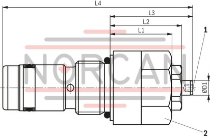
| 6 | 25 | 29 | 33.5 | 77 | 6 |
| 10 | 36 | 41 | 45.5 | 109 | 6 |
|
1 |
Internal hexagon SW3 |
|
2 |
NG6: Hexagon SW27; MA = 40 Nm |
|
NG10: Hexagon SW41; MA = 120 Nm |
Mounting cavity according to DIN ISO 7789
Dimensions in mm
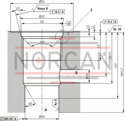
Mounting cavity according to DIN ISO 7789
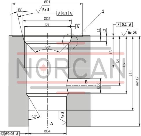
Dimensions in mm
|
NG |
L1 |
L2 |
L3 |
L4 |
L5 |
L6 1) |
L7 |
ØD1 |
ØD2 |
D3 |
ØD4 |
ØD5 |
||||||
|
mm |
mm |
mm |
mm |
mm |
mm |
mm |
mm |
mm |
mm |
mm |
mm |
mm |
mm |
mm |
mm |
|||
| 6 | 0.5 | 2.4 | + 0.4 | 17 | 24 | - 4 | 28 | ± 0.1 | 38.5 | 45 | + 0.2 | 34 | 23.8 | ± 0.1 | M22 x 1,5 | 19 | H7 | 7 |
| 10 | 0.5 | 3.1 | + 0.4 | 23 | 32 | - 4 | 39 | ± 0.4 | 55 | 65 | - | 46 | 35.4 | ± 0.1 | M33 x 2 | 29 | H8 | 11 |
| 1) | Depth of fit |
|
1 |
according to DIN 3852-W |