

BOSCH REXROTH
R900581526
$381.59 USD
- BOSCH REXROTH
- Material:R900581526
- Model:Z2FS6A2-4X/1QV
Quantity in stock: 0
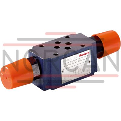
The Bosch Rexroth Z2FS6A2-4X/1QV (R900581526) is a high-performance industrial hydraulic valve designed for reliable throttling of flow to a set value. This mechanically actuated valve falls under the product group ID ZFS, indicating its role as a twin throttle check valve in sandwich plate design. It is tailored to limit the main or pilot flow for one or two actuator ports effectively. This model features direct actuation with a setscrew that includes a lock nut for fine adjustment, ensuring precise control over hydraulic flow. It comes with the spool symbol A A or A A, signifying its configuration and capability to handle maximum pressure demands efficiently. The Z2FS6A2-4X/1QV offers various connection options, including sandwich plate mounting conforming to NFPA T..R D Size CETOP D and ISO standards, which facilitate easy integration into existing hydraulic systems. The valve is equipped with two throttle check valves arranged symmetrically, allowing controlled flows in one direction while enabling free return flow in the opposite direction. The design ensures that whether supply throttling or discharge occurs depends on the installation position of the valve. For velocity adjustments of actuators, this twin throttle check valve can be placed between directional valves and subplates. Similarly, it can be used between pilot control valves and main valves for switching time adjustments when dealing with pilot-operated directional valves. The Bosch Rexroth Z2FS6A2-4X/1QV is crafted to accommodate a maximum operating pressure and flow rate that ensures compatibility with various industrial applications. It also features FKM seals compatible with an array of hydraulic fluids such as HL, HLP, HLPD, HVLP, HVLPD, HETG, HEES, HEPG, HFDU, and HFDR. With multiple adjustment types like setscrew with lock nut and protective cap or lockable rotary knob with scale among others, this model offers versatility in controlling fluid dynamics within hydraulic systems.
Size 6, A1 → A2 or A2 → A1, mechanically actuated
Industrial hydraulic valve in a high performance range. Reliable throttling of the flow to setting value.
Unpacked Weight: 0.97671 kg
The valve type Z2FS is a twin throttle check valve in sandwich plate design. It is used for the main or pilot flow limitation of one or two actuator ports.
Two throttle check valves aligned symmetrically to each other limit flows in one direction and allow free return flow in the opposite direction.
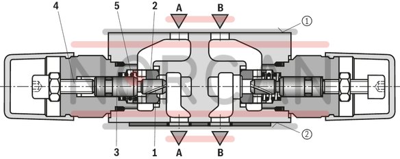
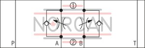
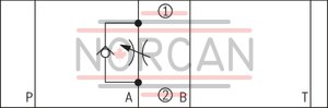
In case of supply throttling, the hydraulic fluid is directed through channel A➀ via throttling point (1) formed by the valve seat (2) and the throttle spool (3) to actuator A➁. The throttle spool (3) can be axially adjusted via the setscrew (4) for adjustment of the throttling point (1).
The hydraulic fluid return flow from actuator A➁ displaces the valve seat (2) against the spring (5) in the direction of the throttle spool (3) and enables the unobstructed flow as check valve. Depending on the installation position, the throttling effect may occur in supply or discharge.
Main flow limitation (Version "2Q")
For actuator velocity adjustment (main flow limitation), the twin throttle check valve is installed between the directional valve and the subplate.
Pilot flow limitation (Version "1Q")
With pilot-operated directional valves, the twin throttle check valve can be applied for switching time adjustment (pilot flow limitation). In this case, it is installed between the pilot control valve and the main valve.
Type Z2FS 6 –2…
(Supply throttling)
|
➀ |
component side |
|
➁ |
plate side |
| Direct actuated |
| Setscrew with lock nut |
| Fine adjustment |
| Component series 4X |
| Maximum flow 80 l/min |
| Size 6 |
| Maximum operating pressure 315 bar |
| Data Sheet | Download Data Sheet |
| Manual | Download Manual |
| Manual | Download Manual |
| Manual | Download Manual |
| Manual | Download Manual |
| Manual | Download Manual |
| Spool symbol | A1 → A2 or A2 → A1 |
| Max. pressure | 350 |
| Productgroup ID | 9,10,11,12,13,14 |
| Number of ports | 4 |
| Type of actuation | with mechanical actuation |
| Size | 6 |
| Max. flow | 80 |
| Type of connection | Sandwich plate |
| Connection diagram NFPA | NFPA T3.5.1 R2-2002 D03 |
| Size_CETOP | D03 |
| Connection diagram | ISO 4401-03-02-0-05 |
| Number of switching positions | 2 |
| Weight | 0.97671 |
| Seals | FKM |
| Hydraulic fluid | HL,HLP,HLPD,HVLP,HVLPD,HETG,HEES,HEPG,HFDU,HFDR |
|
01 |
02 |
03 |
04 |
05 |
06 |
07 |
08 |
09 |
||
|
Z2FS |
6 |
– |
4X |
/ |
* |
|
01 |
Twin throttle check valve, sandwich plate design |
Z2FS |
|
02 |
Size 6 |
6 |
|
03 |
Throttle check valve side A and B |
– 1) |
|
Throttle check valve side A |
A |
|
|
Throttle check valve side B |
B |
|
|
Adjustment type |
||
|
04 |
Setscrew with lock nut and protective cap |
2 |
|
Lockable rotary knob with scale |
3 2) |
|
|
Spindle with internal hexagon and scale |
5 |
|
|
Rotary knob with scale |
7 |
|
|
05 |
Component series 40 … 49 (40 … 49: unchanged installation and mounting dimensions) |
4X |
|
06 |
With fine adjustment |
1Q |
|
Standard version |
2Q |
|
|
Seal material |
||
|
07 |
NBR seals |
no code |
|
FKM seals |
V |
|
|
Observe compatibility of seals with hydraulic fluid used. (Other seals upon request) |
||
|
08 |
no code |
|
|
With locating hole |
/60 3) |
|
|
09 |
Further details in the plain text |
* |
| 1) Identical adjustment types on sides A and B | |
| 2) H-key with material no. R900008158 is included in the scope of delivery. | |
| 3) Locking pin ISO 8752-3x8-St, material no. R900005694 (separate order) |
Preferred types and standard units are contained in the EPS (standard price list).
general
|
Size |
6 | ||
|
Weight (approx.) |
kg |
0.8 | |
|
Installation position |
any | ||
|
Ambient temperature range |
°C |
-20 … +80 | |
hydraulic
|
Size |
6 | ||
|
Maximum operating pressure |
bar |
315 | |
|
Maximum flow |
l/min |
80 | |
|
Hydraulic fluid |
see table | ||
|
Hydraulic fluid temperature range |
°C |
-20 … +80 | |
|
Viscosity range |
mm²/s |
10 … 800 | |
|
Maximum admissible degree of contamination of the hydraulic fluid 1) |
Class 20/18/15 according to ISO 4406 (c) | ||
| 1) | The cleanliness classes specified for the components must be adhered to in hydraulic systems. Effective filtration prevents faults and simultaneously increases the life cycle of the components. For the selection of the filters, see www.boschrexroth.com/filter. |
|
Hydraulic fluid |
Classification |
Suitable sealing materials |
Standards |
|
|
Mineral oils and related hydrocarbons |
HL, HLP, HLPD |
NBR, FKM |
DIN 51524 |
|
|
Environmentally compatible |
Insoluble in water |
HETG |
NBR, FKM |
ISO 15380 |
|
HEES |
FKM |
|||
|
Soluble in water |
HEPG |
FKM |
ISO 15380 |
|
|
Containing water |
Water-free |
HFDU, HFDR |
FKM |
ISO 12922 |
|
Containing water |
HFC (Fuchs Hydrotherm 46M, Petrofer Ultra Safe 620) |
NBR |
ISO 12922 |
|
|
Important information on hydraulic fluids! For further information and data on the use of other hydraulic fluids, please refer to data sheet 90220 or contact us! There may be limitations regarding the technical valve data (temperature, pressure range, life cycle, maintenance intervals, etc.)!Flame-resistant – containing water: Maximum operating pressure 210 bar Maximum hydraulic fluid temperature 60 °C Expected life cycle as compared to HLP hydraulic oil 30 % to 100 % |
||||
For applications outside these parameters, please consult us!
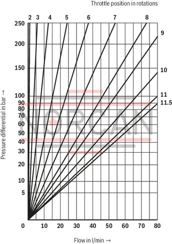
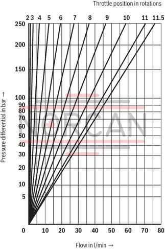
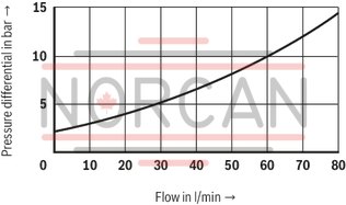
(measured with HLP46, ϑOil = 40 ±5 °C)
Δp-qV characteristic curves (Version "2Q")
Δp-qV characteristic curves (Version "1Q")
Δp-qV characteristic curves for Z2FS 6 ... via open check valve with closed throttle
Supply throttling
Type Z2FS 6 –…
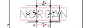
Type Z2FS 6 B…
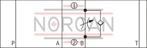
Discharge throttling
Type Z2FS 6 –…
Type Z2FS 6 A…
|
➀ |
component side |
|
➁ |
plate side |
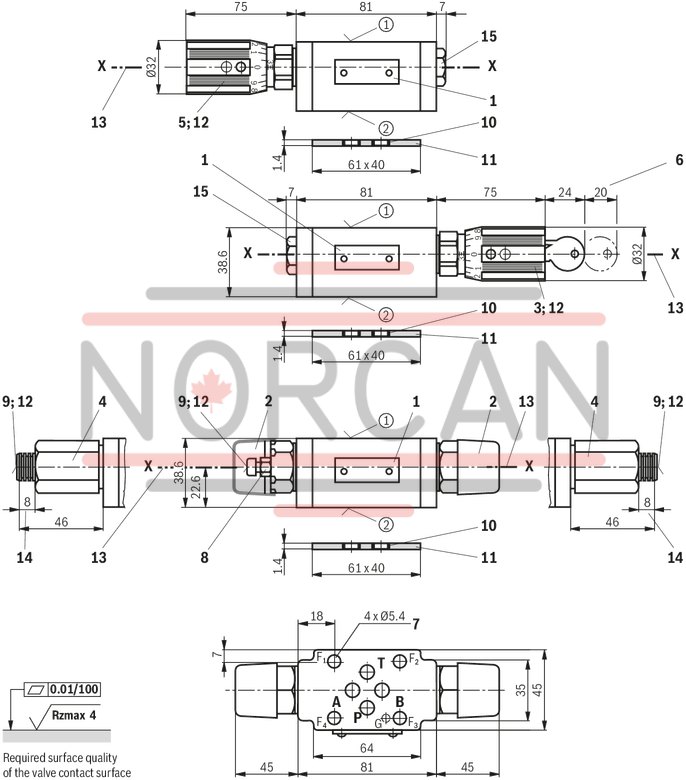
Dimensions in mm
|
➀ |
Component side – porting pattern according to ISO 4401-03-02-0-05 (with locating hole Ø3 x 5 mm deep) |
|
➁ |
plate side – porting pattern according to DIN 24340 form A (without locating hole), or ISO 4401-03-02-0-05 (with locating hole for locking pin ISO 8752-3x8-St; version "/60") |
|
1 |
Name plate |
|
2 |
Adjustment type "2" |
|
3 |
Adjustment type "3" |
|
4 |
Adjustment type "5" |
|
5 |
Adjustment type "7" |
|
6 |
Space required to remove the key |
|
7 |
Valve mounting bores |
|
8 |
Lock nut SW10 |
|
9 |
Setscrew/spindle for flow cross-section adjustment (internal hexagon SW5) |
|
10 |
Same seal rings for ports A, B, P, T |
|
11 |
Seal ring plate |
|
12 |
for all adjustment types: Left rotation = higher flow Right rotation = lower flow |
|
13 |
Modification from discharge to supply control is realized by rotation of the device around axis "X" – "X" |
|
14 |
Stroke |
|
15 |
Plug screw SW22 |
Notice!
Length and tightening torque of the valve mounting screws must be calculated according to the components mounted under and over the sandwich plate valve.
Valve mounting screws (separate order)
4 hexagon socket head cap screws ISO 4762 - M5 - 10.9