


BOSCH REXROTH
R900598324
- BOSCH REXROTH
- Material:R900598324
- Model:4WMM 10 EB3X/
Due to extremely high demand, please call 877-366-7226 for availability
The Bosch Rexroth 4WMM 10 EB3X/ (R900598324) is a manually actuated directional spool valve designed for controlling the start, stop, and direction of fluid flow within a hydraulic system. This particular model features a robust housing, a hand lever for actuation, a control spool, and one or two return springs that maintain the spool's position when deenergized. The valve is engineered to remain in either a central or initial position by these springs, with the exception of version O. The control spool can be shifted to the required position using the hand lever, allowing for precise control over fluid dynamics within the system. The 4WMM 10 EB3X/ model includes a detent feature (indicated by "DXF" in other types), ensuring stable operation and maintaining the selected spool position even after the lever is released. Additionally, this valve may require a throttle insert under certain operating conditions where flow rates during switching exceed the valve's performance limits. This insert helps to modulate flow and protect the valve from potential damage due to excessive flow rates. The porting pattern of this Bosch Rexroth valve conforms to ISO standards, ensuring compatibility with various hydraulic systems. Its size and component series X designation indicate its capacity for handling maximum operating pressures and flows—specific details about these capabilities are provided upon order inquiry. Overall, the Bosch Rexroth 4WMM 10 EB3X/ offers reliable manual control for hydraulic applications where precise manipulation of fluid direction and flow is necessary. Its construction and features make it suitable for various hydraulic applications that require manual intervention with dependable performance.
Valves of type WMM are manually actuated directional spool valves.
They control the start, stop and direction of a flow.
The directional valves basically consist of housing (1), one type of actuation (2.1) (hand lever), control spool (3) and one or two return springs (4).
When de-energized, the control spool (3) is held in the central position or in the initial position by the return springs (4) (except for version "O").
The control spool (3) is moved to the desired spool position by means of the types of actuation.
Type 4WMM 10 D5X/F/... (with detent)
Type 4WMM 10 E5X/...

Throttle insert
The use of a throttle insert is required when, due to prevailing operating conditions, flows occur during the switching processes which exceed the performance limit of the valve.
|
01 |
02 |
03 |
04 |
05 |
06 |
07 |
08 |
09 |
10 |
11 |
||
|
WMM |
10 |
5X |
/ |
/ |
– |
* |
|
01 |
3 main ports |
3 |
||
|
4 main ports |
4 |
|||
|
Types of actuation |
||||
|
02 |
Manually: hand lever |
WMM |
||
|
03 |
Size 10 |
10 |
||
|
04 |
Symbols e. g. C, E, EA, EB, etc.; for the possible version, see Symbols and Types of actuation |
|||
|
05 |
Component series 50 … 59 (50 … 59: unchanged installation and connection dimensions) |
5X |
||
|
06 |
With spring return |
no code |
||
|
With detent |
F |
|||
|
Corrosion protection |
||||
|
07 |
Standard corrosion protection |
no code |
||
|
Improved corrosion protection (720 h salt spray test according to EN ISO 9227) |
J4 |
|||
|
Throttle insert1) |
||||
|
08 |
Without throttle insert |
no code |
||
|
With throttle insert: |
||||
|
Connection |
Throttle Ø in mm |
|||
|
0,8 mm |
1,0 mm |
1,2 mm |
||
|
P |
B08 |
B10 |
B12 |
|
|
A |
H08 |
H10 |
H12 |
|
|
B |
R08 |
R10 |
R12 |
|
|
A and B |
N08 |
N10 |
N12 |
|
|
T 2) |
X08 |
X10 |
X12 |
|
|
Further throttle insert diameters upon request. |
||||
|
Seal material |
||||
|
09 |
NBR seals |
M |
||
|
FKM seals |
V |
|||
|
Seals for HFC hydraulic fluids |
MH |
|||
|
Observe compatibility of seals with hydraulic fluid used. |
||||
|
Pilot oil port |
||||
|
10 |
Whitworth pipe thread G1/4 |
‒ |
||
|
11 |
Further details in the plain text |
* |
||
| 1) When the admissible valve performance limit is exceeded, throttle inserts are to be installed (see Performance limits). | |
| 2) When throttle inserts are used in channel T, the pressure in the working ports and in case of connection to the tank chambers must not exceed 210 bar. |
general
|
Size |
10 | ||
|
Weight |
Valve with one actuation cylinder |
kg |
3.6 |
|
Valve with two actuation cylinders |
kg |
3.6 | |
|
Operating force |
with detent "F" |
N |
30 … 40 |
|
With spring return |
N |
18 … 20 | |
|
Installation position |
any | ||
|
Ambient temperature range |
NBR seals |
°C |
-20 … +70 |
|
FKM seals |
°C |
-15 … +70 | |
|
Storage temperature range |
°C |
-20 … +50 | |
hydraulic
|
Size |
10 | ||
|
Maximum operating pressure |
Port P |
bar |
350 |
|
Port A |
bar |
350 | |
|
Port B |
bar |
350 | |
|
Port T 1) |
bar |
210 | |
|
Maximum flow |
l/min |
160 | |
|
Hydraulic fluid |
see table | ||
|
Hydraulic fluid temperature range 2) |
NBR seals |
°C |
-20 … +80 |
|
FKM seals |
°C |
-15 … +80 | |
|
Viscosity range |
mm²/s |
2.8 … 500 | |
|
Maximum admissible degree of contamination of the hydraulic fluid 3) |
Class 20/18/15 according to ISO 4406 (c) | ||
| 1) | With symbols A or B, port T must be used as leakage oil connection if the operating pressure exceeds the admissible tank pressure. |
| 2) | at the valve working ports of the valve |
| 3) | The cleanliness classes specified for the components must be adhered to in hydraulic systems. Effective filtration prevents faults and simultaneously increases the life cycle of the components. For the selection of the filters, see www.boschrexroth.com/filter. |
|
Hydraulic fluid |
Classification |
Suitable sealing materials |
Standards |
|
|
Mineral oils and related hydrocarbons |
HL, HLP, HLPD, HVLP, HVLPD |
NBR, FKM |
DIN 51524 |
|
|
Bio-degradable |
Insoluble in water |
HETG |
NBR, FKM |
VDMA 24568 |
|
HEES |
FKM |
|||
|
Soluble in water |
HEPG |
FKM |
VDMA 24568 |
|
|
Containing water |
Water-free |
HFDU, HFDR |
FKM |
ISO 12922 |
|
Containing water |
HFC (Fuchs Hydrotherm 46M, Petrofer Ultra Safe 620) |
NBR
|
ISO 12922 |
|
|
Important information on hydraulic fluids! For further information and data on the use of other hydraulic fluids, please refer to data sheet 90220 or contact us! There may be limitations regarding the technical valve data (temperature, pressure range, life cycle, maintenance intervals, etc.)!Flame-resistant – containing water: Maximum pressure differential per control edge 50 bar. Pressure pre-loading at the tank port >20% of the pressure differential; otherwise, increased cavitation Life cycle compared to operation with mineral oil HL, HLP 50 to 100 % |
||||
For applications outside these parameters, please consult us!
(measured with HLP46, ϑOil = 40 ±5 °C)
Δp-qV characteristic curves


|
Symbol |
Direction of flow |
|||
|
P ‒ A |
P ‒ B |
A ‒ T |
B ‒ T |
|
|
A; B |
6 |
6 |
‒ |
‒ |
|
C |
1 |
2 |
5 |
7 |
|
D |
2 |
2 |
5 |
7 |
|
E |
17 |
16 |
19 |
21 |
|
F |
2 |
3 |
22 |
23 |
|
G |
4 |
4 |
24 |
24 |
|
H |
14 |
14 |
20 |
21 |
|
J |
3 |
3 |
9 |
11 |
|
J73 |
22 |
21 |
23 |
24 |
|
L |
3 |
3 |
9 |
9 |
|
M |
14 |
14 |
6 |
8 |
|
P |
17 |
14 |
20 |
23 |
|
Q |
16 |
17 |
4 |
8 |
|
R |
18 |
21 |
18 |
24 |
|
T |
18 |
4 |
10 |
24 |
|
U |
3 |
3 |
6 |
11 |
|
V |
17 |
17 |
18 |
20 |
|
W |
upon request |
|||
|
Central position: |
|||||
|
Symbol |
Direction of flow |
||||
|
P ‒ A |
P ‒ B |
B ‒ T |
A ‒ T |
P ‒ T |
|
|
H |
12 |
12 |
13 |
13 |
15 |
Notice!
The specified performance limits are valid for use with two directions of flow (e. g. from P to A and simultaneous return flow from B to T).
Due to the flow forces acting within the valves, the admissible performance limit may be considerably lower with only one direction of flow (e. g. from P to A while port B is blocked)!
In such use cases, please consult us!
Performance limits (measured with HLP46, ϑOil = 40 ±5 °C)


|
With spring return “–” |
|
|
Characteristic curve |
Symbol |
|
1 |
C, D, E, J, J73, L, M, Q, U, V, W |
|
2 |
H |
|
3 |
T, G |
|
With detent "F" |
|
|
Characteristic curve |
Symbol |
|
4 |
C, D, E, J, J73, L, M, Q, U |
|
5 |
T, G, H |


| 1) | Example:Symbol E with spool position “a” → ordering code ..EA..Symbol E with spool position “b" → ordering code ..EB.. |
Size 16
Dimensions in mm
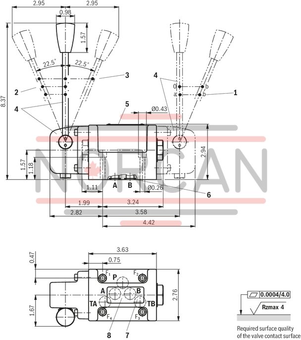
Dimensions in mm

|
1 |
Valves with 2 spool positions, symbol B and .B |
|
2 |
Valves with 2 switching positions, symbol A, C, D .A |
|
3 |
Valves with 3 switching positions |
|
4 |
Cover and hand lever |
|
5 |
Name plate |
|
6 |
Identical seal rings for port A, B, P, TA, TB |
|
7 |
Additional port TB can optionally be used |
|
8 |
Porting pattern according to ISO 4401-05-04-0-05 |
Notices!
Deviating from ISO 4401, port T is called TA and port T1 is called TB in this data sheet. For valves with 2 switching positions and symbols B and .B, the hand lever is installed on valve side B. The dimensions are nominal dimensions which are subject to tolerances.