

BOSCH REXROTH
R900926536
$1,721.34 USD
- BOSCH REXROTH
- Material:R900926536
- Model:LFA32DR2-7X/210
Quantity in stock: 0
The Bosch Rexroth LFA32DR2-7X/210 (R900926536) is a high-quality valve cover designed for precise manual pressure reduction in hydraulic systems. This component is specifically crafted to work with way cartridge valves and ensures a reliable reduction of pressure in conjunction with such valves as indicated by its hydraulic symbol. The LFA32DR2-7X/210 features a spool symbol symbolizing its DR type and can withstand maximum pressure levels as denoted in its product specifications. With a size and type of actuation that allows for manual pressure reduction, this model is engineered for subplate mounting, facilitating seamless integration into hydraulic systems. Its connection diagram follows the ISO standard, ensuring compatibility with a wide range of equipment. The valve cover has a weight that confirms its robust construction, while the NBR seals provide excellent resistance to hydraulic fluids such as HL, HLP, HLPD, HVLP, HVLPD, and HFC. The LFA32DR2-7X/210 valve cover operates with a rest position that is closed to maintain system integrity when not actively adjusting pressure. The design allows for the realization of different pressure functions by combining it with cartridge valves. When engaged in the pressure reducing function with an opening characteristic, it works alongside a pressure limitation cartridge valve type LC..DBD... The pilot oil travels from port A through the supply orifice and the open pilot control valve to side B, allowing flow from A to B until the set pressure is reached and then maintaining the reduced pressure at port B. In summary, this Bosch Rexroth control cover enables sophisticated control over hydraulic pressures within systems requiring dependable and precise operation. Its compatibility with standardized components makes it versatile for various applications where manual adjustment of hydraulic pressures is necessary.
Size 32, manual pressure reduction
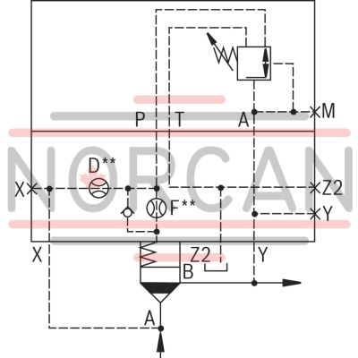
Control cover for 2-way cartridge valves Reliable reduction of the pressure in connection with a 2-way cartridge valve according to the hydraulic symbol.
Unpacked Weight: 5.08 kg
General
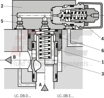
2-way cartridge valves for pressure functions are pilot-operated valves in seat or spool design. The power section designed as cartridge valve (1) is installed into a receiving hole standardized according to DIN ISO 7368 and closed with a control cover (2).
The pilot control valve (4) for manual or electrically proportional pressure adjustment is integrated into the control cover (2) or is installed on the control cover (2) as pilot valve with mounting dimensions according to DIN 24 340.
By combination of cartridge valves with the control covers, different pressure functions can be realized. .
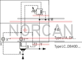
Pressure reducing function
Rest position closed
For the pressure reducing function with opening characteristic, a pressure limitation cartridge valve (type LC..DB40D...) and a control cover with a pressure reducing pilot control valve (type LFA..DR...) are applied. The pilot oil is directed from port A via the supply orifice and the opened pilot control valve to side B.
The main spool is opened and the flow from port A to port B is released.
On reaching the set pressure, the spool is closed and the pressure at port B is reduced according to the pressure-flow characteristics. Potential pressure increases on the secondary side are discharged to the tank via the 3rd way of the pilot control valve. Set-up of a directional valve enables realization of an additional blocking function (type LFA..DRW...).
| Valve cover |
| Size 16 … 100 |
| Maximum operating pressure 420 bar |
| Data Sheet | Download Data Sheet |
| 3D CAD | Download 3D CAD |
| Manual | Download Manual |
| Manual | Download Manual |
| Manual | Download Manual |
| Manual | Download Manual |
| Manual | Download Manual |
| Spool symbol | Symbol DR |
| Max. pressure | 350 |
| Productgroup ID | 9,10,11,12,13,14 |
| Type of actuation | Manual pressure reduction |
| Size | 32 |
| Type of connection | Subplate mounting |
| Connection diagram | ISO 7368 |
| Weight | 5.08 |
| Seals | NBR |
| Hydraulic fluid | HL,HLP,HLPD,HVLP,HVLPD,HFC |
Control cover for pressure reducing function
|
01 |
02 |
03 |
04 |
05 |
06 |
07 |
||
|
LFA |
DR |
‒ |
7X |
/ |
|
Type |
||
|
01 |
Control cover LFA |
LFA |
|
Size |
||
|
02 |
NG 16 |
16 |
|
NG 25 |
25 |
|
|
NG 32 |
63 |
|
|
NG 40 |
40 |
|
|
NG 50 |
50 |
|
|
NG 63 |
63 |
|
|
Version |
||
|
03 |
Pressure reducing function - Main spool in rest position closed (LC..DB 40 D..- separate order) |
DR |
|
Adjustment type for pressure adjustment |
||
|
04 |
Rotary knob |
1 |
|
Sleeve with hexagon and protective cap |
2 |
|
|
Lockable rotary knob with scale, incl. H-key |
3 |
|
|
Rotary knob with scale |
4 |
|
|
Component series |
||
|
05 |
Component series 70 ... 79 (70 ... 79: unchanged installation and connection dimensions) |
7X |
|
Pressure rating DBmax. (observe admissible pressure of the pilot control valve) |
||
|
06 |
Set pressure up to 25 bar |
025 |
|
Set pressure up to 75 bar |
075 |
|
|
Set pressure up to 150 bar |
150 |
|
|
Set pressure up to 210 bar |
210 |
|
|
Set pressure up to 315 bar |
315 |
|
|
Seal material |
||
|
07 |
NBR seals |
no code |
|
FKM seals |
V |
|
Additional preferred types and standard units are specified in the EPS (standard price list).
Main spool in rest position closed - LC..DB 40 D..- separate order
|
Orifice symbol |
Symbol in ordering code |
|||
|
A** |

|
A** |

|
This orifice is designed as screw-type orifice. If an orifice is to be installed, the respective code letter with the orifice Ø in 1/10 mm has to be entered in the type designation. Example: A12 = Orifice with Ø1.2 mm in channel A. |
|
Ø1,2 |

|

|
This orifice is designed as bore. No specifications are made in the type designation. (Orifice Ø in mm) |
|
|
Z12 |

|

|
This orifice is designed as screw-type orifice. This is a standard orifice. No specifications are made in the type designation. (Orifice Ø in 1/10 mm) |
|
general
|
Size |
16 | 25 | 32 | 40 | 50 | 63 |
hydraulic
|
Size |
16 | 25 | 32 | 40 | 50 | 63 | ||
|
Hydraulic fluid |
see table | |||||||
|
Hydraulic fluid temperature range |
NBR seals |
°C |
-30 … +80 | |||||
|
FKM seals |
°C |
-20 … +80 | ||||||
|
Viscosity range |
mm²/s |
2.8 … 380 | ||||||
|
Maximum admissible degree of contamination of the hydraulic fluid 1) |
Class 20/18/15 according to ISO 4406 (c) | |||||||
| 1) | The cleanliness classes specified for the components must be adhered to in hydraulic systems. Effective filtration prevents faults and simultaneously increases the life cycle of the components. For the selection of the filters, see www.boschrexroth.com/filter. |
|
Hydraulic fluid |
Classification |
Suitable sealing materials |
Standards |
|
|
Mineral oil |
HL, HLP |
FKM, NBR |
DIN 51524 |
|
|
Bio-degradable |
Insoluble in water |
HEES (synthetic esters) |
FKM |
VDMA 24568 |
|
HETG (rape seed oil) |
FKM, NBR |
|||
|
Soluble in water |
HEPG (polyglycols) |
FKM |
VDMA 24568 |
|
|
Other hydraulic fluids on request |
||||
Control cover
|
Size |
16 | 25 | 32 | 40 | 50 | 63 | |||
|
maximum admissible operating pressure in port ... |
...X (primary pressure) |
bar |
315 | ||||||
|
...Y (secondary pressure = max. set pressure) |
bar |
315 | |||||||
|
...Z2 |
static |
bar |
60 | ||||||
|
at pressure control |
depressurized (up to ≈ 2 bar) | ||||||||
For applications outside these parameters, please consult us!
LFA..DR.-7X/...NG 16

LFA..DR.-7X/...NG 25, 32

LFA..DR.-7X/...NG 40, 50

LFA..DR.-7X/...NG 63

Attention!
Control covers type LFA..DR... are combined with 2-way cartridge valves type LC..DB 40 D... (see ordering code).
The control covers are equipped with standard orifice fitting – optimized in our test area. Orifice specification in the type key is not necessary. Deviating operating conditions may require respective adjustment of the orifice size. The orifices are designed as screw-type orifices.
Orifice representation in symbol
(basic symbol) - Pressure reducing function
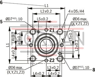
Installation bore and connection dimensions according to ISO 7368
NG16 ... 63
Dimensions in mm
|
5 |
Bore for locating pin (cover pin assembled according to DIN 24 342) |
|
6 |
Information on porting pattern NG 16: Length L1 (axis x–y bores) is 80 mm |
|
8 |
Bore for locating pin at function as main pressure relief valve (reposition cover pin for assembly accordingly) |
NG 16, 25, 32
Dimensions in mm

|
1 |
Port X optionally as threaded port (at NG 16...50) |
|
3.1 |
Port Z1 optionally as threaded port (at LFA..DREZ.. , LFA..DREWZ..., NG 25..63) |
|
4 |
Locating pin |
|
9.1 |
Name plate (NG16) |
|
9.2 |
Name plate (NG 25, 32) |
NG 40, 50
Dimensions in mm

|
1 |
Port X optionally as threaded port (at NG 16...50) |
|
2 |
Port Y optionally as threaded port (at NG 40, 50) |
|
3.1 |
Port Z1 optionally as threaded port (at LFA..DREZ.. , LFA..DREWZ..., NG 25..63) |
|
3.2 |
Port Z2 optionally as threaded port (at NG 40, 50, 63) |
|
4 |
Locating pin |
|
9.3 |
Name plate (NG 40, 50, 63) |
|
10 |
Check valve (at NG 63 orifice F in poppet) |
NG63
Dimensions in mm
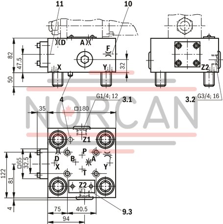
|
3.1 |
Port Z1 optionally as threaded port (at LFA..DREZ.. , LFA..DREWZ..., NG 25..63) |
|
3.2 |
Port Z2 optionally as threaded port (at NG 40, 50, 63) |
|
4 |
Locating pin |
|
9.3 |
Name plate (NG 40, 50, 63) |
|
10 |
Check valve (at NG 63 orifice F in poppet) |
|
11 |
At control cover NG 63, logic element NG 16 |
NG16 ... 63
Dimensions in mm

|
5.1 |
Adjustment element "4" |
|
5.2 |
Adjustment element "3" |
|
6 |
Adjustment element "2" |
|
7 |
Adjustment element "1" |
|
8 |
direct operated pressure reducing valve (included in the scope of delivery) |
|
9 |
Name plate of the pressure reducing valve |
|
11 |
Valve mounting screws M5x50 DIN 912-10.9 MA = 8.9 Nm are included in the scope of delivery of the control cover |
|
12 |
Pressure gauge connection G1/4; 12 mm deep; internal hexagon SW6 |
|
13 |
Space required to remove the key |
|
14 |
Control cover |
|
15 |
Lock nut SW24 |
|
16 |
at type .../315 → 50 mm |
Notice:
The dimensions are nominal dimensions which are subject to tolerances.
|
Mounting screws (included in scope of delivery) |
|||
|
Hexagon socket head cap screw according to DIN 912-10.9 |
|||
|
NG |
Quantity |
Dimensions |
Tightening torque in Nm |
|
16 |
4 |
M 8 x 45 |
32 |
|
25 |
4 |
M 12 x 50 |
110 |
|
32 |
4 |
M 16 x 60 |
270 |
|
40 |
4 |
M 20 x 70 |
520 |
|
50 |
4 |
M 20 x 80 |
520 |
|
63 |
4 |
M 30 x 100 |
1800 |
|
NG |
H1 |
H2 |
H3 |
L1 |
L2 |
L3 |
L7 |
|
mm |
mm |
mm |
mm |
mm |
mm |
mm |
|
| 16 |
40 - |
17 - |
15 |
65 - |
80 | 36.5 | 49 |
| 25 |
40 - |
19 - |
24 |
85 - |
85 | 49 | 59 |
| 32 |
50 - |
26 - |
28 |
100 - |
100 | 56.5 | 66.5 |
Valve dimensions
|
NG |
Ø Orifice A** |
Ø Orifice X** 1) |
Ø Orifice F** |
Ø Orifice D** |
L8 |
L9 |
L10 |
L11 |
L12 |
||||||
|
.../315 |
.../315 |
.../315 |
.../315 |
.../315 |
.../315 |
||||||||||
|
mm |
mm |
mm |
mm |
mm |
mm |
mm |
mm |
mm |
mm |
mm |
mm |
mm |
mm |
mm |
|
| 16 | - | 2.5 | - | 0.8 1) | 0.8 1) | 22 | 30.5 | 119.5 | 116.5 | 143.5 | 140.5 | 99.5 | 96.5 | 99.5 | 96.5 |
| 25 | - | - | 0.8 1) | 3 2) | 1.8 2) | 5.5 | 14 | 131 | 128 | 155 | 152 | 111 | 108 | 111 | 108 |
| 32 | - | - | 1 1) | 3 2) | 1.8 2) | - | 6 | 123.5 | 120.5 | 148.5 | 145.5 | 103.5 | 100.5 | 103.5 | 100.5 |
| 40 | - | - | 1.2 1) | 3 2) | 1.8 2) | - | - | 111 | 108 | 135 | 132 | 91 | 88 | 91 | 88 |
| 50 | - | - | 1.5 1) | 3 2) | 1.8 2) | - | - | 103.5 | 100.5 | 128.5 | 125.5 | 83.5 | 80.5 | 83.5 | 80.5 |
| 63 | 2 1) | - | 1.5 1) | 3 1) | 1.8 1) | - | - | 87.5 | 84.5 | 111.5 | 108.5 | 67.5 | 64.5 | 67.5 | 64.5 |
| 1) | Orifice Ø, orifice M6 conical |
| 2) | Orifice Ø, orifice M8 x 1 conical |
|
NG |
H1 |
H2 |
H3 |
H4 |
H5 |
L1 |
L2 |
L3 |
L4 |
L5 |
L7 |
|
mm |
mm |
mm |
mm |
mm |
mm |
mm |
mm |
mm |
mm |
mm |
|
| 40 |
60 - |
30 - |
32 | 40 | 40 |
125 - |
125 | 72 | 62.5 | 62.5 | 79 |
| 50 |
68 - |
32 - |
34 | 32 | 32 |
140 - |
140 | 80 | 70 | 70 | 86.5 |