
BOSCH REXROTH
R900954078
$3,091.77 USD
- BOSCH REXROTH
- Material:R900954078
- Model:4WRAE6W30-2X/G24K31/A1V
Quantity in stock: 0
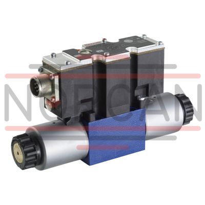
The Bosch Rexroth 4WRAE6W30-2X/G24K31/A1V (R900954078) is a high-performance industrial hydraulic valve designed for reliable control of oil flow direction, in accordance with its spool symbol W. This direct-actuated spool valve features integrated electronics for electrical actuation and is suitable for subplate mounting with connection ports conforming to the ISO standard. The valve operates at a maximum pressure, allowing for a nominal flow rate. Characterized by its size and CETOP D designation, the 4WRAE6W30-2X/G24K31/A1V employs analog connectivity, accepting command values from 0 to 10 V. It is compatible with a variety of hydraulic fluids including HL, HLP, and more, ensuring versatility across different hydraulic systems. The electrical connection utilizes a Connector pole PE according to EN standards, ensuring secure and reliable power supply. The valve's function relies on its housing that includes a control spool balanced by compression springs and actuated by proportional solenoids with central thread. These solenoids are controlled via the integrated electronics without the need for external feedback mechanisms. In its default state, the control spool is centered by the springs but can be shifted proportionally to the input signal by energizing one of the solenoids. This model specifically comes with two spool positions (type WRA...A...), differentiated from three-position models by having only one proportional solenoid and a plug screw or cover in place of the second solenoid. The design ensures that when de-energized, the control spool returns to its central position due to spring force. Important considerations for installation include maintaining fluid in the tank line and potentially installing a preload valve under certain conditions. With its robust construction and precise electronic control capabilities, this Bosch Rexroth valve is engineered for optimal flow direction management within various industrial hydraulic systems.
Size 6, symbol W, electrical with integrated electronics, 24 V DC
Industrial hydraulic valve in a high performance range, reliable control of oil flow direction according to hydraulic symbol.
Unpacked Weight: 2.221 kg
The 4/2 and 4/3 proportional directional valves are designed as direct operated devices in plate design. Operation by means of proportional solenoids with central thread and detachable coil. The solenoids are controlled via integrated electronics.
Set-up:
The valve basically consists of:
Housing (1) with connection surface Control spool (2) with compression springs (3 and 4) Solenoids (5 and 6) with central thread Integrated electronics (7)Function:
With de-energized solenoids (5 and 6), central position of the control spool (2) due to compression springs (3 and 4) Direct actuation of the control spool (2) by energization of one proportional solenoid, e. g. energization of solenoid "b" (6) Control spool (2) is moved to the left in proportion to the electrical input signal Connection from P to A and B to T via orifice-type cross-sections with progressive flow characteristics Switching off of the solenoid (6) Control spool (2) is returned to the central position by the compression spring (3)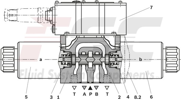
Valve with two spool positions (type 4WRA...A...):
The function of this valve version basically corresponds to the valve with three spool positions. This 2 spool position valve is, however, only equipped with solenoid “a”. Instead of the 2nd proportional solenoid, there is a plug screw (8.1) with NG 6 or a cover (8.2) with NG10.
Notice:
The tank line must not be allowed to run empty. With corresponding installation conditions, a preload valve (preload pressure approx. 2 bar) must be installed.
| Spool valve |
| Direct actuated |
| Maximum flow 75 l/min |
| Size 6, 10 |
| Component series 2X |
| Maximum operating pressure 315 bar |
| Data Sheet | Download Data Sheet |
| 3D CAD | Download 3D CAD |
| Manual | Download Manual |
| Manual | Download Manual |
| Manual | Download Manual |
| Manual | Download Manual |
| Manual | Download Manual |
| Spool symbol | Symbol W |
| Max. pressure | 315 |
| Electrical connection description | Connector 7-pole (6 + PE) according to EN 175201-804 |
| Productgroup ID | 9,10,11,12,13,14 |
| Number of ports | 4 |
| Type of actuation | Electrical with integrated electronics |
| Size | 6 |
| Electrical connector | Connector 7-pole (6 + PE) |
| Max. flow | 42 |
| Type of connection | Subplate mounting |
| Connection diagram NFPA | NFPA T3.5.1 R2-2002 D03 |
| Size_CETOP | D03 |
| Nominal flow | 26 |
| Connection diagram | ISO 4401-03-02-0-05 |
| Supply voltage | 24 VDC |
| Number of switching positions | 3 |
| Weight | 2.221 |
| Seals | FKM |
| Connectivity | Analog, command value ±10 V |
| Hydraulic fluid | HL,HLP,HLPD,HVLP,HVLPD,HETG,HEES,HEPG,HFDU,HFDR |
| Hydraulic fluid | HL,HLP,HLPD,HVLP,HVLPD,HETG,HEES,HEPG,HFDU,HFDR |
|
01 |
02 |
03 |
04 |
05 |
06 |
07 |
08 |
09 |
10 |
11 |
12 |
|||
|
4 |
WRAE |
‒ |
2X |
/ |
G24 |
/ |
* |
|
01 |
4 main ports |
4 |
|
02 |
Proportional directional valve with integrated electronics |
WRAE |
|
03 |
Size 6 |
6 |
|
Size 10 |
10 |
|
|
04 |
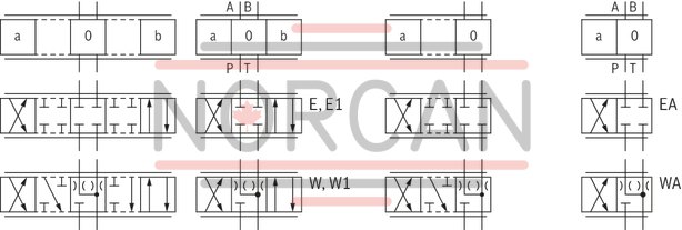
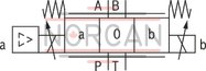
Symbols; for the possible version, see "Symbols/Circuit diagrams" |
E; E1-; W; W1-; EA; WA |
|
Rated flow NG6 |
||
|
05 |
7 l/min |
7 |
|
15 l/min |
15 |
|
|
30 l/min |
30 |
|
|
Rated flow NG10 |
||
|
05 |
30 l/min |
30 |
|
60 l/min |
60 |
|
|
06 |
Component series 20 ... 29 (20 ... 29: unchanged installation and connection dimensions) |
2X |
|
07 |
Supply voltage 24 V |
G24 |
|
Special type of protection |
||
|
08 |
Without special type of protection |
no code |
|
Sea water-resistant |
J 1) |
|
|
Electrical connection |
||
|
09 |
Connector DIN EN 175201-804 |
K31 2) |
|
Electrical interface |
||
|
10 |
Command value ±10 V |
A1 |
|
Command value 4 to 20 mA |
F1 |
|
|
Seal material |
||
|
11 |
NBR seals |
M |
|
FKM seals |
V |
|
|
12 |
Further details in the plain text |
* |
|
1) |
Electrical protection classes on request |
|
|
2) |
Only with NG6: only indicate "K31" for version “J”! |
|
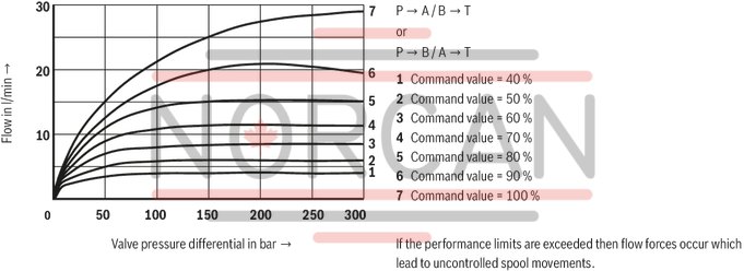
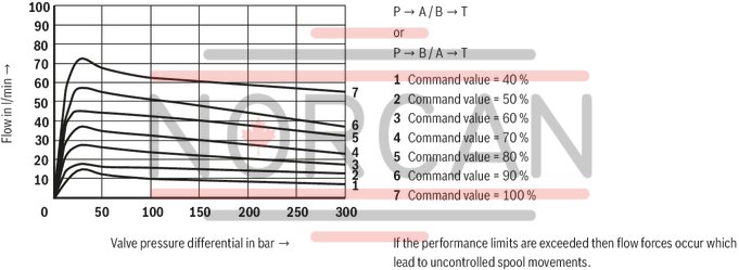
For applications outside these parameters, please consult us!
general
|
Type |
4WRAE | ||
|
Size |
6 | 10 | |
|
Installation position |
any, preferably horizontal | ||
|
Ambient temperature range |
°C |
-20 … +50 | |
|
Storage temperature range |
°C |
-20 … +80 | |
|
Weight |
kg |
2.2 | 6.8 |
hydraulic
|
Size |
6 | 10 | ||
|
Maximum operating pressure |
bar |
315 | ||
|
Maximum operating pressure |
Port P |
bar |
315 | |
|
Port T |
bar |
210 | ||
|
Port A |
bar |
315 | ||
|
Port B |
bar |
315 | ||
|
Maximum flow |
l/min |
42 | 75 | |
|
with double flow |
l/min |
80 | 140 | |
|
Nominal flow |
l/min |
7 15 26 |
30 60 |
|
|
Hydraulic fluid 1) |
Mineral oil (HL, HLP) to DIN 51524 | |||
|
Hydraulic fluid temperature range |
°C |
-20 … +80 | ||
|
preferably |
°C |
+40 … +50 | ||
|
Viscosity range |
mm²/s |
20 … 380 | ||
|
preferably |
mm²/s |
30 … 46 | ||
|
Maximum admissible degree of contamination of the hydraulic fluid, cleanliness class according to ISO 4406 (c) 2) |
Class 20/18/15 according to ISO 4406 (c) | |||
|
Hysteresis |
% |
≤ 5 | ||
|
Range of inversion |
% |
≤ 1 | ||
|
Response sensitivity |
% |
≤ 0.5 | ||
| 1) | Additional hydraulic fluids upon request |
| 2) | The cleanliness classes specified for the components must be adhered to in hydraulic systems. Effective filtration prevents faults and simultaneously increases the life cycle of the components. For the selection of the filters, see www.boschrexroth.com/filter. |
|
Hydraulic fluid |
Classification |
Suitable sealing materials |
Standards |
|
Mineral oils and related hydrocarbons |
HL, HLP |
NBR / FKM |
DIN 51524 |
|
Important information on hydraulic fluids: For more information and data on the use of other hydraulic fluids please contact us. |
|||
electrical
|
Size |
6 | 10 | ||
|
Voltage type |
Direct voltage | |||
|
Maximum solenoid current |
A |
2.5 | ||
|
Maximum current consumption |
of the amplifier |
A |
1.8 | |
|
of the amplifier (impulse current) |
A |
3 | ||
|
Solenoid coil resistance |
Cold value at 20 °C |
Ω |
2 | |
|
Maximum hot value |
Ω |
3 | ||
|
Actuated time |
% |
100 | ||
|
Maximum coil temperature 1) |
°C |
+ 150 | ||
|
Power supply |
VDC |
24 | ||
|
Supply voltage range |
V |
19 … 35 | ||
|
Command value input |
"A1" |
V |
± 10 | |
|
Command value input range |
"F1" |
mA |
4 … 20 | |
| 1) | Due to the surface temperatures occurring at the solenoid coils, the European standards ISO 13732-1 and EN 982 need to be adhered to. |
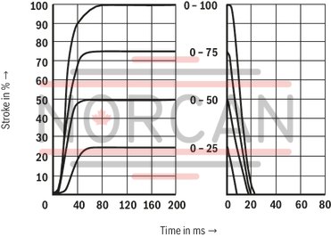
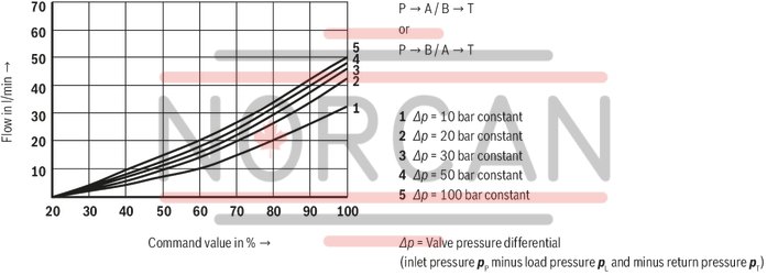
(measured with HLP46, ϑÖl = 40 ±5 °C)
Rated flow 7 l/min at a valve pressure differential of 10 bar
NG6

Rated flow 15 l/min at a valve pressure differential of 10 bar
NG6
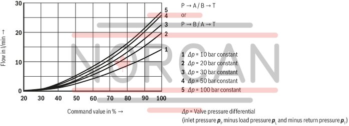
Rated flow 30 l/min at a valve pressure differential of 10 bar
NG6
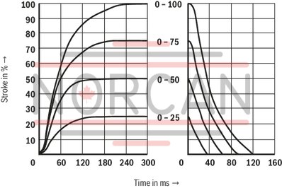
Transition function with stepped electric input signals
NG6
Performance limit rated flow 7 l/min
NG6
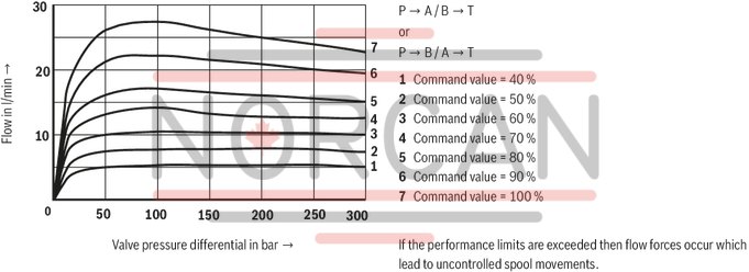
Performance limit rated flow 15 l/min
NG6
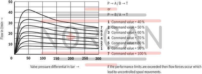
Performance limit rated flow 30 l/min
NG6
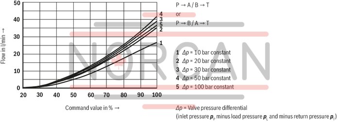
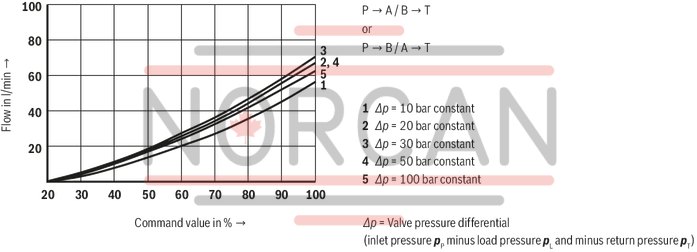
Rated flow 30 l/min at a valve pressure differential of 10 bar
NG10
Rated flow 60 l/min at a valve pressure differential of 10 bar
NG10
Transition function with stepped electric input signals
NG10
Performance limit rated flow 30 l/min
NG10
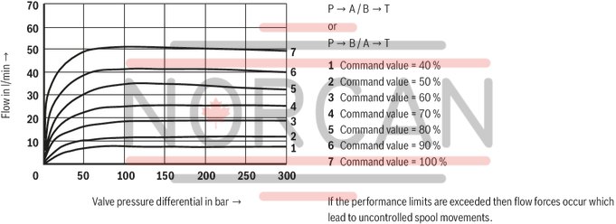
Performance limit rated flow 60 l/min
NG10
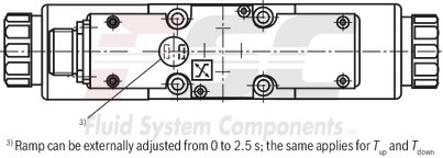
Symbols
|
With control spool symbol E1- and W1-, the following applies: |
|
|
P → A: qvmax |
B → T: qv/2 |
|
P → B: qv/2 |
A → T: qvmax |
|
Notice: |
|
Type 4WRAE
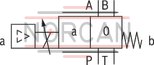
Type 4WRAE...EA;Type 4WRAE...WA
|
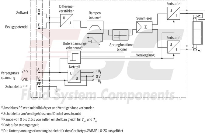
Pin assignment |
Contact |
Signal |
|
Power supply |
A |
24 VDC (19...35 VDC) |
|
B |
GND |
|
|
C |
cannot be used 1) |
|
|
Differential amplifier input (command value) |
D |
Command value (±10 V / 4...20 mA) |
|
E |
Reference potential |
|
|
F |
cannot be used 1) |
|
|
1) |
Contacts C and F must not be connected! |
|
Command value:
Positive command value (0...10 V or 12...20 mA) at D and reference potential at E result in flow from P → A and B → T.
Negative command value (0...-10 V or 12...4 mA) at D and reference potential at E result in flow from P → B and A → T.
With valves with solenoid on side “a” (control spool variant EA and WA), a positive command value at D and reference potential at E (NG6: 4...20 mA and NG10: 12...20 mA) result in flow from P → B and A → T.
Connection cable: Recommendation:
up to 25 m cable length type LiYCY 5 x 0.75 mm²
up to 50 m cable length type LiYCY 5 x 1.0 mm²
External diameter 6.5 … 11 mm
Connect shield on PE only on the supply side
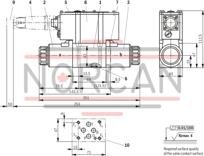
4WRAE 6
Dimensions in mm
|
1 |
Valve housing |
|
2 |
Proportional solenoid "a" |
|
3 |
Proportional solenoid "b" |
|
4 |
Mating connector according to DIN EN 175201-804, separate order |
|
5 |
Name plate |
|
6 |
Identical seal rings for ports A, B, P, and T |
|
7 |
Plug screw for valves with one solenoid (2 spool positions, version "EA" or "WA") |
|
8 |
Integrated electronics (OBE) |
|
9 |
Space required for the connection cable and to remove the mating connector |
|
10 |
Machined valve contact surface; Porting pattern according to ISO 4401-03-02-0-05 (with locating hole) |
Recommended valve mounting screws (separate order):
4 hexagon socket head cap screws ISO 4762 - M5 x 50 - 10.9-flZn-240h-L
tightening torque MA = 7 Nm ± 10%, material no. R913000064 or
4 hexagon socket head cap screws ISO 4762 - M5 x 50 - 10.9
tightening torque MA = 8.9 Nm ± 10%
4WRAE 10
Dimensions in mm
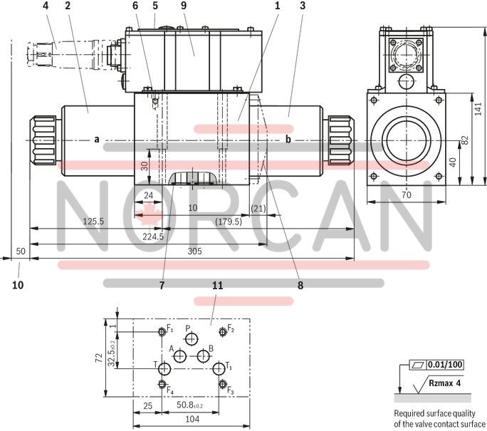
|
1 |
Valve housing |
|
2 |
Proportional solenoid "a" |
|
3 |
Proportional solenoid "b" |
|
4 |
Mating connector according to DIN EN 175201-804, separate order |
|
5 |
Name plate |
|
6 |
Valve bleed screw: Notice: Valves are bled prior to delivery |
|
7 |
Identical seal rings for ports A, B, P and T (T1) |
|
8 |
Cover for valves with one solenoid (2 spool positions, version "EA" or "WA") |
|
9 |
Integrated electronics (OBE) |
|
10 |
Space required for the connection cable and to remove the mating connector |
|
11 |
Machined valve contact surface; Porting pattern according to ISO 4401-05-04-0-05 |
Recommended valve mounting screws (separate order):
4 hexagon socket head cap screws ISO 4762 - M6 x 40 - 10.9-flZn-240h-L
tightening torque MA = 12.5 Nm ± 10 %, material no. R913000058 or
4 hexagon socket head cap screws ISO 4762 - M6 x 40 - 10.9
tightening torque MA = 15.5 Nm ± 10%
Mating connectors for valves with round connector, 6-pole + PE
7P Z31
Mating connectors for valves with round connector, 6-pole + PE
7P Z31
For valves with round connector according to EN 175201-804, 6-pole + PE as well as 6-pole, compatible with VG 95328Data sheet
Spare parts & repair