


BOSCH REXROTH
R900962519
- BOSCH REXROTH
- Material:R900962519
- Model:LC63DB40E7X/V
Quantity in stock: 0
The Bosch Rexroth LC63DB40E7X/V (R900962519) is a sophisticated way cartridge valve designed for pressure functions, tailored to meet various hydraulic control needs. This seat valve is engineered for pressure relief applications without an area difference at port B, ensuring precise operation. It operates through a pilot oil supply orifice that directs the effective pressure to the spring side of the element, allowing the spool to remain closed under spring force until the set pressure is reached. Upon reaching this pressure, the spool opens, and the pressure at port A is limited based on the valve's characteristic curve. For pressure reducing functions, this model employs a control cover with an integrated pilot control valve to regulate flow from port A to port B. The main spool opens to allow flow and closes when the set pressure is achieved, reducing the secondary side's pressure and discharging potential increases in pressure back to the tank. Additionally, it supports pressure sequencing functions which enable a second system's connection based on specific pressures set at an integrated pilot control valve. The pilot oil supply can be external or internal, with depressurization of the pilot control spring chamber to the tank through designated ports. This model also allows for customizable circuits such as one for unloading low-pressure systems upon reaching a set system pressure and another for connecting a second system only when specified conditions are met in the first system. The LC63DB40E7X/V can handle maximum flows as indicated by its size and component series designation. With its versatile configuration options and reliable performance characteristics, this Bosch Rexroth cartridge valve stands out as an essential component in advanced hydraulic systems where precision and adaptability are paramount.
General
2-way cartridge valves for pressure functions are pilot-operated valves in seat or spool design. The power section designed as cartridge valve (1) is installed into a receiving hole standardized according to DIN ISO 7368 and closed with a control cover (2).
The pilot control valve (4) for manual or electrically proportional pressure adjustment is integrated into the control cover (2) or is installed on the control cover (2) as pilot valve with mounting dimensions according to DIN 24 340.
By combination of cartridge valves with the control covers, different pressure functions can be realized. .
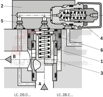
Pressure relief function
The cartridge valve (1) for the pressure relief function (type LC . DB...) is designed as seat valve without area difference (no effective area at port B). The effective pressure at port A is directed via the pilot oil supply orifice (5) to the spring side (6) of the element. Under the pressure set at the pilot control valve (4), the spool (3) is pressure-compensated and closed by the spring force.
On reaching the set pressure, the spool (3) is opened and the pressure at port A is limited according to the pressure-flow characteristics.
Pressure reducing function
Rest position closed
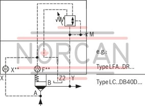
For the pressure reducing function with opening characteristic, a pressure limitation cartridge valve (type LC..DB40D...) and a control cover with a pressure reducing pilot control valve (type LFA..DR...) are applied. The pilot oil is directed from port A via the supply orifice and the opened pilot control valve to side B.
The main spool is opened and the flow from port A to port B is released.
On reaching the set pressure, the spool is closed and the pressure at port B is reduced according to the pressure-flow characteristics. Potential pressure increases on the secondary side are discharged to the tank via the 3rd way of the pilot control valve. Set-up of a directional valve enables realization of an additional blocking function (type LFA..DRW...).
Pressure sequencing functions
This function enables pressure-dependent connection of a second system.
The required switching pressure is set at the pilot control valve integrated into the control cover.
The pilot oil supply may either be realized externally (pilot oil port X) or internally (from port A via pilot oil ports X or Z2).
The pilot control spring chamber is directed via ports Y or Z1, depressurized to the tank.
Circuit examples
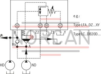
Example 1: (Circuit for pressure-dependent unloading of the low-pressure system)
In the illustrated circuit, the system is supplied via a high-pressure and a low-pressure pump. The system pressure pS acts externally from the high-pressure side via pilot oil port X on the pilot control valve, which sets the low-pressure side to depressurized circulation after the set pressure value is reached. The check valve RV (not included in the scope of delivery) prevents the connection of the high-pressure system with the now depressurized low-pressure system.
On reaching the pressure set at the pilot control spring, the pilot control valve is switched and the spring chamber of the main valve to the tank is unloaded. The main spool is opened and the connection A to B is released.
With the version LFA..DZW..., the required switching position can be selected besides the hydraulic circuit by means of an electrically operated pilot control valve (not included in the scope of delivery of the control cover LFA..DZ...).
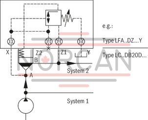
Example 2: (Circuit for pressure-dependent connection of a second system)
With this circuit, system 2 is not connected before the pressure in system 1 complies with the specified value. Pilot oil discharge is realized internally from port A of the main valve.
|
01 |
02 |
03 |
04 |
05 |
06 |
07 |
|
|
LC |
DB |
/ |
|
Type |
||
|
01 |
Cartridge valve |
LC |
|
Size |
||
|
02 |
NG 16 |
16 |
|
NG 25 |
25 |
|
|
NG 32 |
32 |
|
|
NG 40 |
40 |
|
|
NG 50 |
50 |
|
|
NG 63 |
63 |
|
|
NG 80 |
80 |
|
|
NG 100 |
100 |
|
|
Version |
||
|
03 |
Pressure relief function |
DB |
|
Cracking pressure |
||
|
04 |
Cracking pressure 0 bar (without spring) |
00 |
|
Cracking pressure approx. 2 bar |
20 |
|
|
Cracking pressure approx. 3 bar 1) |
30 |
|
|
Cracking pressure approx. 4 bar |
40 |
|
|
Cracking pressure approx. 5 bar (NG16, 25 and 32 only) |
50 |
|
|
Cracking pressure approx. 8 bar 2) |
80 |
|
|
Damping |
||
|
05 |
Seat piston without orifice (standard version) |
E |
|
Seat spool piston without orifice (standard version) |
D |
|
|
Seat piston without orifice |
A |
|
|
Piston without precision grooves |
B |
|
|
Component series |
||
|
06 |
Component series 70 ... 79 (70 ... 79: unchanged installation and connection dimensions) 3) |
7X |
|
Component series 60 … 69 (60 … 69: unchanged installation and connection dimensions) 4) |
6X |
|
|
Seal material |
||
|
07 |
NBR seals |
no code |
|
FKM seals |
V |
|
| 1) Cracking pressure 3.0 bar NG16 only, for set-up of a pilot-operated pressure relief valve type DBC . -5X/…SO187 | |
| 2) Special installation space required (see compression spring dimensions) | |
| 3) Component series 7X for sizes 16...63 | |
| 4) Component series 6X for sizes 80 and 100 | |
Additional preferred types and standard units are specified in the EPS (standard price list).
|
Hydraulic fluid |
Classification |
Suitable sealing materials |
Standards |
|
|
Mineral oil |
HL, HLP |
FKM, NBR |
DIN 51524 |
|
|
Bio-degradable |
Insoluble in water |
HEES (synthetic esters) |
FKM |
VDMA 24568 |
|
HETG (rape seed oil) |
FKM, NBR |
|||
|
Soluble in water |
HEPG (polyglycols) |
FKM |
VDMA 24568 |
|
|
Other hydraulic fluids on request |
||||
hydraulic
|
Size |
16 | 25 | 32 | 40 | 50 | 63 | 80 | 100 | ||
|
Maximum operating pressure |
Port A |
bar |
420 | |||||||
|
Port B |
bar |
420 | ||||||||
|
Maximum flow (recommendation) |
Seat-cartridge valve "E" and "A" |
l/min |
300 | 450 | 600 | 1000 | 1600 | 2500 | 4500 | 7000 |
|
Spool-cartridge valve "D" and "B" |
l/min |
175 | 300 | 450 | 700 | 1400 | 1750 | 3200 | 4900 | |
|
Hydraulic fluid |
Mineral oil (HL, HLP) according to DIN 51524; fast biodegradable hydraulic fluids according to VDMA 24568 ; HETG (rape seed oil); HEPG (polyglycols); HEES (synthetic esters), other hydraulic fluids on request | |||||||||
|
Hydraulic fluid temperature range |
NBR seals |
°C |
-30 … +80 | |||||||
|
FKM seals |
°C |
-20 … +80 | ||||||||
|
Viscosity range |
mm²/s |
2.8 … 380 | ||||||||
|
Maximum admissible degree of contamination of the hydraulic fluid 1) |
Class 20/18/15 according to ISO 4406 (c) | |||||||||
| 1) | The cleanliness classes specified for the components must be adhered to in hydraulic systems. Effective filtration prevents faults and simultaneously increases the life cycle of the components. For the selection of the filters, see www.boschrexroth.com/filter. |
For applications outside these parameters, please consult us!
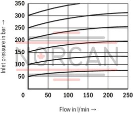
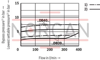
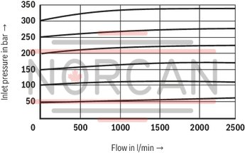
(measured with HLP46, ϑOil = 40 ±5 °C)
The characteristic curves were measured with external, depressurized pilot oil return. Due to the internal pilot oil return, the inlet pressure increases by the output pressure present in port B.
manual pressure adjustment
Type LC 16 DB.E… (with seat piston)
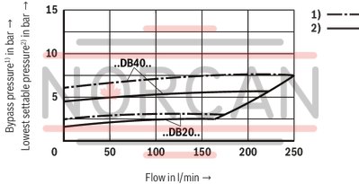
manual pressure adjustment
Type LC 16 DB.E… (with seat piston)
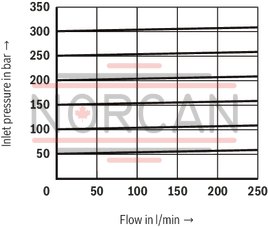
manual pressure adjustment
Type LC 16 DB.D… (seat-spool valve)
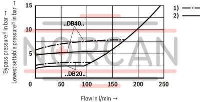
manual pressure adjustment
Type LC 16 DB.D… (seat-spool valve)
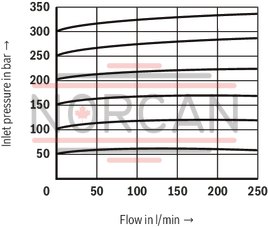
electrically proportional pressure adjustment
Type LC 16 DB.E… (with seat piston)
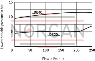
electrically proportional pressure adjustment
Type LC 16 DB.E… (with seat piston)
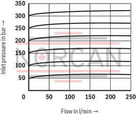
electrically proportional pressure adjustment
Type LC 16 DB.D… (seat-spool valve)
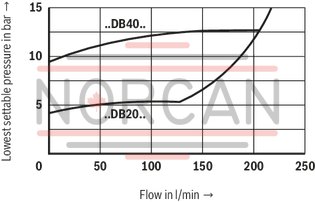
electrically proportional pressure adjustment
Type LC 16 DB.D… (seat-spool valve)
(measured with HLP46, ϑOil = 40 ±5 °C)
The characteristic curves were measured with external, depressurized pilot oil return. Due to the internal pilot oil return, the inlet pressure increases by the output pressure present in port B.
manual pressure adjustment
Type LC 25 DB.E… (with seat piston)
manual pressure adjustment
Type LC 25 DB.E… (with seat piston)
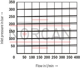
manual pressure adjustment
Type LC 25 DB.D… (with seat-spool piston)
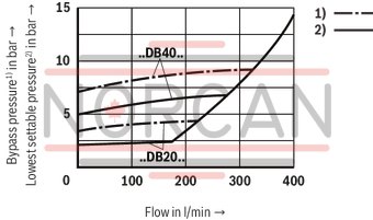
manual pressure adjustment
Type LC 25 DB.D… (with seat-spool piston)
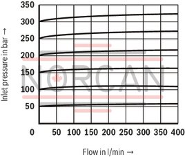
electrically proportional pressure adjustment
Type LC 25 DB.E… (with seat piston)
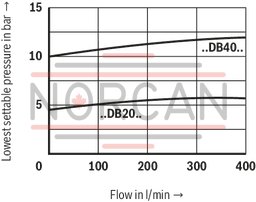
electrically proportional pressure adjustment
Type LC 25 DB.E… (with seat piston)
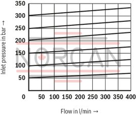
electrically proportional pressure adjustment
Type LC 25 DB.D… (with seat-spool piston)
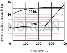
electrically proportional pressure adjustment
Type LC 25 DB.D… (with seat-spool piston)
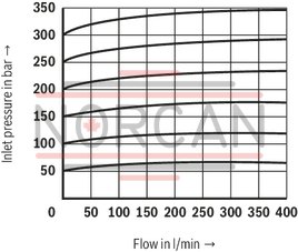
(measured with HLP46, ϑOil = 40 ±5 °C)
The characteristic curves were measured with external, depressurized pilot oil return. Due to the internal pilot oil return, the inlet pressure increases by the output pressure present in port B.
manual pressure adjustment
Type LC 32 DB.E… (with seat piston)
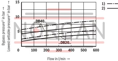
manual pressure adjustment
Type LC 32 DB.E… (with seat piston)
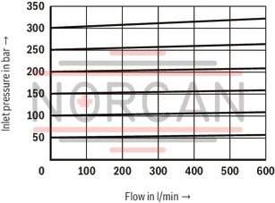
manual pressure adjustment
Type LC 32 DB.D… (with seat-spool piston)
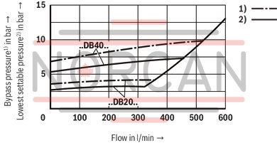
manual pressure adjustment
Type LC 32 DB.D… (with seat-spool piston)
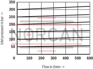
electrically proportional pressure adjustment
Type LC 32 DB.E… (with seat piston)
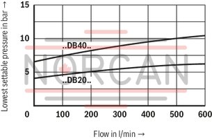
electrically proportional pressure adjustment
Type LC 32 DB.E… (with seat piston)
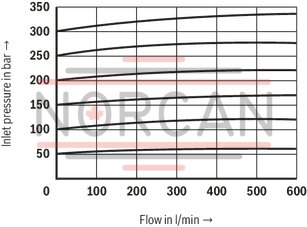
electrically proportional pressure adjustment
Type LC 32 DB.D… (with seat-spool piston)
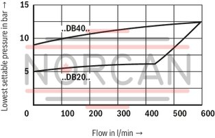
electrically proportional pressure adjustment
Type LC 32 DB.D… (with seat-spool piston)
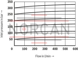
(measured with HLP46, ϑOil = 40 ±5 °C)
The characteristic curves were measured with external, depressurized pilot oil return. Due to the internal pilot oil return, the inlet pressure increases by the output pressure present in port B.
manual pressure adjustment
Type LC 40 DB.E… (with seat piston)
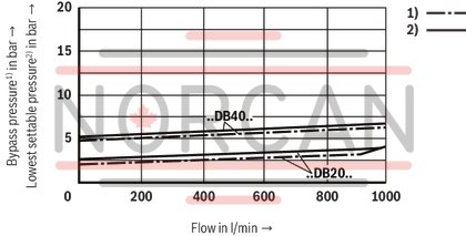
manual pressure adjustment
Type LC 40 DB.E… (with seat piston)
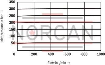
manual pressure adjustment
Type LC 40 DB.D… (with seat-spool piston)
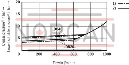
manual pressure adjustment
Type LC 40 DB.D… (with seat-spool piston)
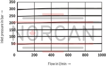
electrically proportional pressure adjustment
Type LC 40 DB.E… (with seat piston)
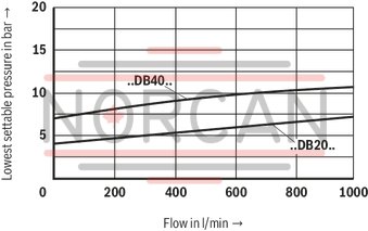
electrically proportional pressure adjustment
Type LC 40 DB.E… (with seat piston)
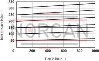
electrically proportional pressure adjustment
Type LC 40 DB.D… (with seat-spool piston)
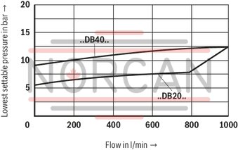
electrically proportional pressure adjustment
Type LC 40 DB.D… (with seat-spool piston)
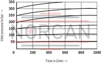
(measured with HLP46, ϑOil = 40 ±5 °C)
The characteristic curves were measured with external, depressurized pilot oil return. Due to the internal pilot oil return, the inlet pressure increases by the output pressure present in port B.
manual pressure adjustment
Type LC 50 DB.E… (with seat piston)
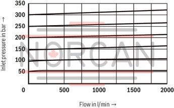
manual pressure adjustment
Type LC 50 DB.D… (with seat-spool piston)
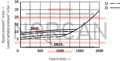
manual pressure adjustment
Type LC 50 DB.E… (with seat piston)
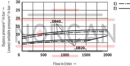
manual pressure adjustment
Type LC 50 DB.D… (with seat-spool piston)
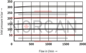
electrically proportional pressure adjustment
Type LC 50 DB.D… (with seat-spool piston)
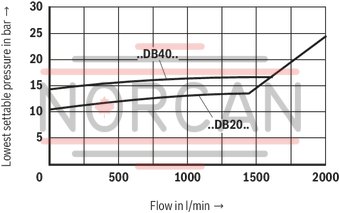
electrically proportional pressure adjustment
Type LC 50 DB.E… (with seat piston)
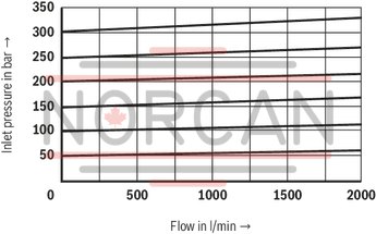
electrically proportional pressure adjustment
Type LC 50 DB.E… (with seat piston)
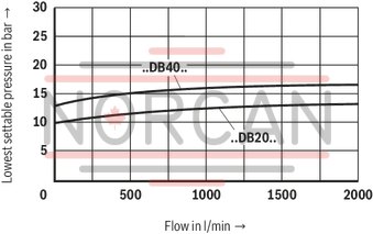
electrically proportional pressure adjustment
Type LC 50 DB.D… (with seat-spool piston)
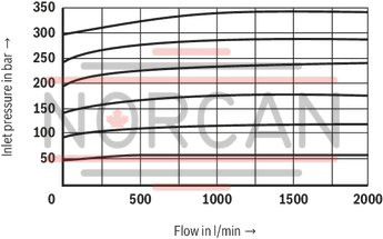
(measured with HLP46, ϑOil = 40 ±5 °C)
The characteristic curves were measured with external, depressurized pilot oil return. Due to the internal pilot oil return, the inlet pressure increases by the output pressure present in port B.
manual pressure adjustment
Type LC 63 DB.E… (with seat piston)
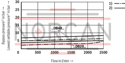
manual pressure adjustment
Type LC 63 DB.E… (with seat piston)
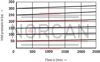
manual pressure adjustment
Type LC 63 DB.D… (with seat-spool piston)
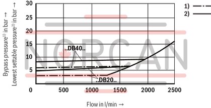
manual pressure adjustment
Type LC 63 DB.D… (with seat-spool piston)
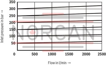
electrically proportional pressure adjustment
Type LC 63 DB.E… (with seat piston)
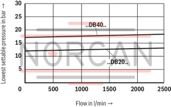
electrically proportional pressure adjustment
Type LC 63 DB.E… (with seat piston)
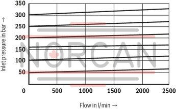
electrically proportional pressure adjustment
Type LC 63 DB.D… (with seat-spool piston)
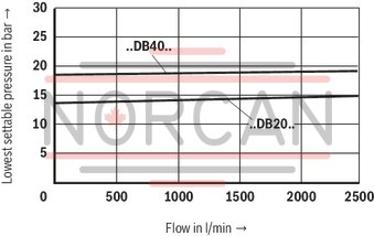
electrically proportional pressure adjustment
Type LC 63 DB.D… (with seat-spool piston)
|
Version "E" |
Version “D” |
||
|
Area ratio |
Area ratio |
Area ratio |
Area ratio |


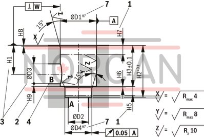
Installation bore and connection dimensions according to ISO 7368
Dimensions in mm
|
1 |
Depth of fit |
|
2 |
Control dimension |
|
3 |
If a different diameter is used for port B than ØD3 or (ØD3*), the distance from the cover support surface to the bore center must be calculated. |
|
4 |
Port B may be positioned around the central axis of port A. However, it must be observed that the mounting bores and the control bores are not damaged. |
|
7 |
At Ø ≤45 mm → Fitting H8 admissible |
|
NG |
ØD1 |
ØD2 |
ØD3/(ØD3*) |
ØD4 |
ØD5 |
ØD6 1) |
ØD7 |
H1/(H1*) |
H2 |
H3 |
H4 |
H5 |
H6 |
H7 |
H8 |
H9 |
L1 |
ØL1 |
L2 |
ØL2 |
L3 |
L4 |
L5 |
W |
||||
|
mm |
mm |
mm |
mm |
mm |
mm |
mm |
mm |
mm |
mm |
mm |
mm |
mm |
mm |
mm |
mm |
mm |
mm |
mm |
mm |
mm |
mm |
mm |
mm |
|||||
| 16 | 32 |
H7 - |
16 |
16 25 |
25 |
H7 - |
M8 | 4 | 4 |
H13 - |
34 29.5 |
56 | 43 | - | 20 | 11 | 2 | 20 | 2 | 0.5 |
65 80 |
- | 46 | - | 23 | 25 | 10.5 | 0.05 |
| 25 | 45 |
H7 - |
25 |
25 32 |
34 |
H7 - |
M12 | 6 | 6 |
H13 - |
44 40.5 |
72 | 58 | - | 25 | 12 | 2.5 | 30 | 2.5 | 1 |
85 - |
- | 58 | - | 29 | 33 | 16 | 0.05 |
| 32 | 60 |
H7 - |
32 |
32 40 |
45 |
H7 - |
M16 | 8 | 6 |
H13 - |
52 48 |
85 | 70 | - | 35 | 13 | 2.5 | 30 | 2.5 | 1.5 |
102 - |
- | 70 | - | 35 | 41 | 17 | 0.1 |
| 40 | 75 |
H7 - |
40 |
40 50 |
55 |
H7 - |
M20 | 10 | 6 |
H13 - |
64 59 |
105 | 87 | - | 45 | 15 | 3 | 30 | 3 | 2.5 |
125 - |
- | 85 | - | 42.5 | 50 | 23 | 0.1 |
| 50 | 90 |
H7 - |
50 |
50 63 |
68 |
H7 - |
M20 | 10 | 8 |
H13 - |
72 65.5 |
122 | 100 | - | 45 | 17 | 3 | 35 | 4 | 2.5 |
140 - |
- | 100 | - | 50 | 58 | 30 | 0.1 |
| 63 | 120 |
H7 - |
63 |
63 80 |
90 |
H7 - |
M30 | 12 | 8 |
H13 - |
95 86.5 |
155 | 130 | - | 65 | 20 | 4 | 40 | 4 | 3 |
180 - |
- | 125 | - | 62.5 | 75 | 38 | 0.2 |
| 80 | 145 |
H7 - |
80 |
80 100 |
110 |
H7 - |
M24 | 16 | 10 |
H13 - |
130 120 |
205 | 175 | ± 0.2 | 50 | 25 | 5 | 40 | 5 | 4.5 |
- - |
250 | - | 200 | - | - | - | 0.2 |
| 100 | 180 |
H7 - |
100 |
100 125 |
135 |
H7 - |
M30 | 20 | 10 |
H13 - |
155 142 |
245 | 210 | ± 0.2 | 63 | 29 | 5 | 50 | 5 | 4.5 |
- - |
300 | - | 245 | - | - | - | 0.2 |
| 1) | Maximum dimension |