

BOSCH REXROTH
R900962528
- BOSCH REXROTH
- Material:R900962528
- Model:2FRE 6 B-2X/2QEK4RV-3
Due to extremely high demand, please call 877-366-7226 for availability
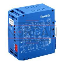
The Bosch Rexroth 2FRE 6 B-2X/2QEK4RV-3 (R900962528) is a state-of-the-art proportional flow control valve designed for precise flow regulation in hydraulic systems. This valve features a way function that allows it to maintain a specified flow rate regardless of pressure and temperature changes, ensuring consistent performance. The unit is composed of a durable housing, a high-precision proportional solenoid with an inductive position transducer, and a metering orifice coupled with a pressure compensator. Equipped with an optional check valve, the 2FRE 6 B-2X/2QEK4RV-3 model provides versatility in application by allowing free return flow from port B to A. The valve's command value potentiometer facilitates the setting of the flow rate, which is then translated into orifice adjustment through the solenoid and monitored by the position transducer. Any deviations from the set command value are automatically corrected by the position control system. The pressure compensator plays a crucial role in this setup by maintaining constant pressure at the metering orifice, thus enabling load-compensated flow control. This valve also boasts low temperature drift due to its well-designed metering orifice. In case of power failure or disconnection at the position transducer, safety is ensured as the metering orifice will close. For smooth operation start-up and shut-down, ramp functions are integrated into the electrical amplifier that delays opening and closing of the metering orifice. Additionally, with an appropriate rectifier sandwich plate installed beneath it, this valve can regulate both supply and return flows from an actuator. Designed for subplate mounting conforming to ISO standards and featuring axially movable position transducer coils for straightforward zero-point calibration without affecting control electronics, this Bosch Rexroth proportional flow control valve represents precision engineering for advanced hydraulic applications. It supports maximum operating pressures up to bar and can handle maximum flows up to l/min, making it suitable for various industrial requirements.
Proportional flow control valves of the 2FRE ... type comprise a 2-way function. They are capable of controlling a flow indicated by the electrical command value in a pressure- and temperature-compensated manner.
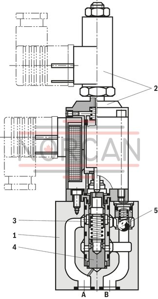
The set-up basically consists of a housing (1), proportional solenoid with inductive position transducer (2), metering orifice (3), pressure compensator (4) as well as check valve (5), optional.
Proportional flow control valve, version “B…RV” (without external closing, with check valve)
The flow setting is determined by the indication (0 to 100%) at the command value potentiometer. Via the amplifier as well as the proportional solenoid, the indicated command value has an effect on the adjustment of the metering orifice (3). The position of the metering orifice (3) is recorded by the inductive position transducer. Any existing variations from the command value are corrected by the position control.
The pressure compensator (4) keeps the pressure drop at the metering orifice (3) at a constant value at all times. Thus, the flow is load-compensated.
The low temperature drift is the result of the favorable design of the metering orifice. With command value 0%, the metering orifice is closed. In the event of a power failure or cable break at the inductive position transducer, the metering orifice closes.
From the command value 0%, a smooth start-up is possible. Via two ramps in the electric amplifier, the metering orifice can be opened and closed with delay.
Via the check valve (5), a free return flow from B to A is possible. With an additional rectifier sandwich plate of the Z4S 6... type under the proportional flow control valve, the supply and return flow from the actuator can be regulated.
Type 2FRE 6 B-2X/...RV
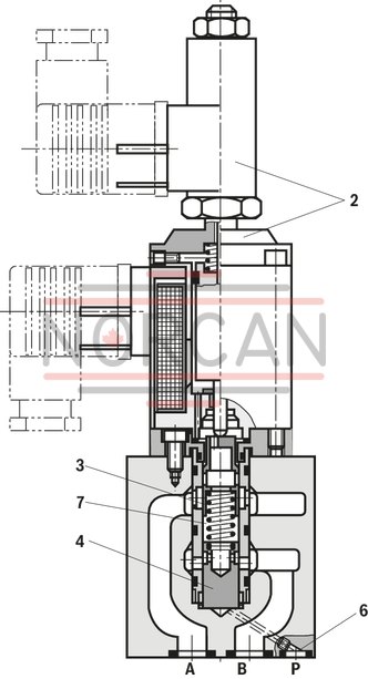
Proportional flow control valve, version “A…MV” (with external closing, without check valve)
The function of this valve is basically the same as that of valve type "B...RV".
For the start-up jump suppression with open metering orifice (3) (command value > 0%), a closing of the pressure compensator (4) is provided via port P (6). The internal connection between port A and the pressure compensator (4) is abandoned. Via the external port P (6), the pressure in P upstream to the directional valve (8) has an impact on the pressure compensator (4) and keeps the latter in its closed position against the spring force (7). If the directional valve (8) is switched from P to B, the pressure compensator (4) moves from the closed position into the control position and the start-up jump is thus prevented.
Type 2FRE 6 A-2X/...MV

|
01 |
02 |
03 |
04 |
05 |
06 |
07 |
08 |
09 |
||
|
2FRE |
6 |
- |
2X |
/ |
K4 |
V |
* |
|
01 |
Proportional flow control valve in 2-way version |
2FRE |
|
|
02 |
Size 6 |
6 |
|
|
03 |
With external closing of the pressure compensator (suppression of the start-up jump) |
A |
|
|
Without external closing of the pressure compensator |
B |
||
|
04 |
Component series 20 ... 29 (20 ... 29: unchanged installation and connection dimensions) |
2X |
|
|
rated flow A → B, flow characteristic |
|||
|
05 |
Linear |
Up to 1 l/min |
1L |
|
Up to 2 l/min |
2L |
||
|
Up to 8 l/min |
8L |
||
|
Progressive |
Up to 3 l/min |
3Q |
|
|
Up to 6 l/min |
6Q |
||
|
Up to 10 l/min |
10Q |
||
|
Up to 16 l/min |
16Q |
||
|
Up to 25 l/min |
25Q |
||
|
Progressive with rapid traverse |
Fine control range up to 2 l/min |
2QE |
|
|
Electrical connection |
|||
|
06 |
Individual connection |
||
|
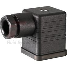
Without mating connector, connector DIN EN 175301-803-A (proportional solenoid) and GSA20 (position transducer) |
K41) |
||
|
07 |
With check valve |
R |
|
|
Without check valve |
M |
||
|
Seal material |
|||
|
08 |
FKM seals |
V |
|
|
Observe compatibility of seals with hydraulic fluid used. (Other seals upon request) |
|||
|
09 |
Further details in the plain text |
* |
|
| 1) | Mating connectors, separate order, see "Accessories" and datasheet 08006. |
For applications outside these parameters, please consult us!
general
|
Size |
6 | |
|
Component series |
2X | |
|
Installation position |
Any | |
|
Weight |
kg |
1.8 |
|
Storage temperature range |
°C |
-20 … +80 |
|
Ambient temperature range |
°C |
-20 … +50 |
hydraulic (Measured with HLP46, ϑOil = 40±5 °C)
|
Size |
6 | ||
|
Maximum operating pressure |
Port A |
bar |
210 |
|
Minimum pressure differential |
bar |
6 … 10 | |
|
Pressure differential with free return flow B → A |
See characteristic curve | ||
|
Pressure/flow-dependence of input/output pressure |
See characteristic curve | ||
|
Temperature drift |
See characteristic curve | ||
|
Hydraulic fluid |
see table | ||
|
Hydraulic fluid temperature range |
°C |
-20 … +80 | |
|
Viscosity range |
mm²/s |
15 … 380 | |
|
Maximum admissible degree of contamination of the hydraulic fluid, cleanliness class according to ISO 4406 (c) 1) |
Class 20/18/15 according to ISO 4406 (c) | ||
|
Hysteresis |
of qVmax |
% |
< ± 1 |
|
Repetition accuracy |
of qVmax |
% |
< 1 |
|
Manufacturing tolerance |
at command value 33 % |
% |
≤ ± 3 |
|
at command value 100 % |
% |
≤ ± 5 | |
| 1) | The cleanliness classes specified for the components must be adhered to in hydraulic systems. Effective filtration prevents faults and simultaneously increases the life cycle of the components. For the selection of the filters, see www.boschrexroth.com/filter. |
hydraulic
|
Version |
1L | 2L | 8L | 3Q | 6Q | 10Q | 16Q | 25Q | 2QE | ||
|
Maximum flow |
l/min |
1 | 2 | 8 | 3 | 6 | 10 | 16 | 25 | ||
|
Minimum flow |
100 bar |
ml/min |
25 | 50 | 15 | 25 | 50 | 70 | 100 | 15 | |
|
210 bar |
ml/min |
25 | 50 | 25 | 50 | 70 | 100 | 25 | |||
|
Maximum leakage flow, Δp A → B with a command value of 0% 1) |
50 bar |
ml/min |
4 | 6 | 4 | 6 | 7 | 10 | 4 | ||
|
100 bar |
ml/min |
5 | 8 | 5 | 8 | 10 | 15 | 5 | |||
|
210 bar |
ml/min |
7 | 12 | 7 | 12 | 15 | 22 | 7 | |||
| 1) | Measured with ν = 41 mm2/s and ϑ = 50 °C |
|
Hydraulic fluid |
Classification |
Suitable sealing materials |
Standards |
Data sheet |
|
Mineral oils |
HL, HLP |
FKM |
DIN 51524 |
90220 |
|
Flame-resistant - water-free |
HFDU (glycol base) |
FKM |
ISO 12922 |
90222 |
|
Important information on hydraulic fluids: For more information and data on the use of other hydraulic fluids please contact us. There may be limitations regarding the technical valve data (temperature, pressure range, life cycle, maintenance intervals, etc.). The ignition temperature of the hydraulic fluid used must be 50 K higher than the maximum surface temperature. |
||||
electrical, proportional solenoid
|
Voltage type |
Direct voltage | ||
|
Maximum current per solenoid |
A |
1.5 | |
|
Coil resistance |
Cold value at 20 °C |
Ω |
5.4 |
|
Maximum hot value |
Ω |
8.2 | |
|
Duty cycle |
% |
100 | |
|
Electrical connection 1) |
Connector according to DIN EN 175301-803-A | ||
|
Protection class according to DIN EN 60529 2) |
IP65 (with mating connector mounted and locked) | ||
| 1) | Mating connector, separate order |
| 2) | Due to the arising surface temperatures of the solenoid coils, the standards ISO 13732-1 and ISO 4413 are to be observed. |
electrical, inductive position transducer
|
Coil resistance at 20°C |
Total resistance between 1 and 2 |
Ω |
31.5 |
|
Total resistance between 2 and PE |
Ω |
45.5 | |
|
Total resistance between PE and 1 |
Ω |
31.5 | |
|
Electrical connection 1) |
Connector GSA20 | ||
|
Type of protection according to EN 60529 2) |
IP65 (with mating connector mounted and locked) | ||
|
Inductivity |
mH |
6 ... 8 | |
|
Oscillator frequency |
kHz |
2.5 | |
|
Electrical position measurement system |
Differential throttle | ||
|
Nominal stroke |
mm |
3.5 | |
| 1) | Mating connector, separate order |
| 2) | Due to the arising surface temperatures of the solenoid coils, the standards ISO 13732-1 and ISO 4413 are to be observed. |
(measured with HLP46, ϑOil = 40 ±5 °C)
Dependency of the flow from the command value voltage
Flow control of A → B; pnom = 50 bar

Dependency of the flow from the command value voltage
Flow control of A → B; pnom = 50 bar

Dependency of the flow from the command value voltage
Flow control of A → B; pnom = 50 bar

Transition function with stepped command value modification; pnom = 100 bar; version "25Q"

Frequency response characteristic curves; pnom = 100 bar; version "25Q"

Proportional flow control valve; pressure/flow dependence; inlet pressure

Proportional flow control valve; pressure/flow dependence; outlet pressure

Temperature dependence (version "25Q" - greatest variation) at Δp = 30 bar

Pressure differential via check valve B → A orifce closed

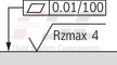
(① = component side, ② = plate side)
|
Proportional flow control valve (simplified, detailed) |
||||
|
Version “B...MV” |
Version “B...RV” |
Version “A...MV" |
Version “A...RV" |
|
|
simplified |

|

|

|

|
|
Detailed |

|

|

|

|
Connection at connector

Connection at mating connector

Dimensions in mm

|
|
Required surface quality of the valve contact surface |
|
1 |
Valve housing |
|
2 |
Proportional solenoid with inductive position transducer |
|
3.1 |
Mating connector for proportional solenoid, separate order |
|
3.2 |
Mating connector for position transducer, separate order |
|
4 |
Space required to remove the mating connector |
|
5 |
Name plate |
|
6.1 |
Identical seal rings for ports A, B, P and blind counterbore |
|
7 |
Port A |
|
8 |
Port B |
|
9 |
Blind counterbore Ø 12.6 mm |
|
10 |
Machined valve contact surface; Porting pattern according to ISO 4401-03-02-0-05 |
Notice:
The dimensions are nominal dimensions which are subject to tolerances.
Subplates (separate order) with porting pattern according to ISO 4401-03-02-0-05, see data sheet 45100.
Valve mounting screws (separate order):
4 hexagon socket head cap screws ISO 4762 - M5 x 30 - 10.9-flZn-240h-L
(friction coefficient 0.09 … 0.14 according to VDA 235-101)
Tightening torque MA = 7 Nm ± 10 %, material no. R913048086
or
4 hexagon socket head cap screws ISO 4762 - M5 x 30 - 10.9
(friction coefficient 0.08 … 0.16 according to VDI 2230 – black)
Tightening torque MA = 8.1 Nm ± 10 %, material no. 2910150205
Notes:
Rectifier sandwich plate impossible in proportional flow control valve, version “A” (with external closing of the pressure compensator). The dimensions are nominal dimensions which are subject to tolerances.Sandwich plates
Z4S 6
Sandwich plates
Z4S 6
Size 6 Maximum operating pressure 210 bar Nominal flow 25 l/minData sheet
Spare parts & repair
Valve amplifiers for proportional flow control valves
VT-MRPA1-150-1X
Valve amplifiers for proportional flow control valves
VT-MRPA1-150-1X
Component series 1X Analog, Modular design For valves: 2FRE6-2XData sheet
Configurator / CAD
Spare parts & repair
Valve amplifiers for proportional flow control valves
VT-VRPA1-150-1X

Valve amplifiers for proportional flow control valves
VT-VRPA1-150-1X
Component series 1X Analog, Euro-card format For valves: 2FRE 6Data sheet
Configurator / CAD
Spare parts & repair
Mating connectors for valves with connector “K4”, without circuitry, standard
3P Z4
Mating connectors for valves with connector “K4”, without circuitry, standard
3P Z4
For valves with connector “K4” according to EN 175301-803 and ISO 4400, 2-pole + PE, “large cubic connector” Mating connectors for valves with one or two solenoids (individual connection)Data sheet
Spare parts & repair