


BOSCH REXROTH
R900964834
- BOSCH REXROTH
- Material:R900964834
- Model:4WRA6EA03-2X/G24N9K4/V
Due to extremely high demand, please call 877-366-7226 for availability
The Bosch Rexroth 4WRA6EA03-2X/G24N9K4/V (R900964834) is a high-performance proportional directional valve designed for direct operation and plate mounting. This device is engineered to control the direction and magnitude of flow in hydraulic systems with precision. It operates using proportional solenoids that feature a central thread and a detachable coil, which are governed by external control electronics. The valve's construction includes a robust housing with connection surfaces, a control spool balanced by compression springs, and the aforementioned solenoids. In its default state, with solenoids de-energized, the control spool is held in the central position by the springs. Upon energization of a solenoid, the control spool is directly actuated, shifting proportionally to the electric input signal to modify flow paths within the system. This particular model of valve offers two spool positions (type WRA...A...) and operates without electrical position feedback. Instead of a second proportional solenoid, it includes either a plug screw or cover depending on size designation NG6 or NG10 respectively. The tank line must be maintained full as per operational requirements; if necessary, a preload valve with an approximate preload pressure of 5 bar should be installed to ensure proper function. Designed for subplate mounting, this valve adheres to ISO porting patterns and is spring-centered for reliable return to neutral. It boasts an impressive maximum operating pressure of 350 bar and can handle maximum flows up to 80 l/min. The Bosch Rexroth 4WRA6EA03-2X/G24N9K4/V is tailored for applications requiring accurate flow control in hydraulic circuits where performance and reliability are critical.
The 4/2 and 4/3 proportional directional valves are designed as direct operated devices in plate design. Operation by means of proportional solenoids with central thread and detachable coil. The solenoids are controlled by external control electronics.
Set-up:
The valve basically consists of:
Housing (1) with connection surface Control spool (2) with compression springs (3 and 4) Solenoids (5 and 6) with central threadFunction:
With de-energized solenoids (5 and 6), central position of the control spool (2) by compression springs (3 and 4) Direct operation of the control spool (2) by energization a proportional solenoid, e.g. control of solenoid "b" (6) Displacement of the control spool (2) to the left, proportionally to the electric input signal Connection from P to A and B to T via orifice-type cross-sections with progressive flow characteristics Switching off the solenoid (6) The compression spring (3) brings the control spool (2) back into the central position
Valve with two spool positions (type 4WRA...A...):
The function of this valve version basically corresponds to the valve with three spool positions. This 2 spool position valve is, however, only equipped with solenoid “a”. Instead of the 2nd proportional solenoid, there is a plug screw (8.1) with NG 6 or a cover (8.2) with NG10.
Notice:
The tank line must not be allowed to run empty. With corresponding installation conditions, a preload valve (preload pressure approx. 2 bar) must be installed.
|
01 |
02 |
03 |
04 |
05 |
06 |
07 |
08 |
09 |
10 |
11 |
|||
|
4 |
WRA |
‒ |
2X |
/ |
G24 |
/ |
* |
|
01 |
4 main ports |
4 |
|
02 |
Proportional directional valve without integrated electronics |
WRA |
|
Size |
||
|
03 |
Size 6 |
6 |
|
Size 10 |
10 |
|
|
04 |
Symbols; for the possible version, see "Symbols/Circuit diagrams" |
E;E1-;W;W1-;EA;WA |
|
Rated flow NG6 |
||
|
05 |
7 l/min |
7 |
|
15 l/min |
15 |
|
|
30 l/min |
30 |
|
|
Rated flow NG10 |
||
|
05 |
30 l/min |
30 |
|
60 l/min |
60 |
|
|
06 |
Component series 20 ... 29 (20 ... 29: unchanged installation and connection dimensions) |
2X |
|
07 |
Supply voltage 24 V |
G24 |
|
Special type of protection |
||
|
08 |
Without special type of protection |
no code |
|
Sea water-resistant |
J 1) |
|
|
Electrical connection |
||
|
09 |
Connector DIN EN 175301-803 |
K4 2) |
|
Seal material |
||
|
10 |
NBR seals |
M |
|
FKM seals |
V |
|
|
11 |
Further details in the plain text |
* |
|
1) |
Electrical protection classes on request |
|
|
2) |
Only with NG6: only indicate "K31" for version “J”! |
|
For applications outside these parameters, please consult us!
general
|
Type |
4WRA | ||
|
Size |
6 | 10 | |
|
Installation position |
any, preferably horizontal | ||
|
Ambient temperature range |
°C |
-20 … +70 | |
|
Storage temperature range |
°C |
-20 … +80 | |
|
Weight |
kg |
2 | 6.6 |
hydraulic
|
Size |
6 | 10 | ||
|
Maximum operating pressure |
bar |
315 | ||
|
Maximum operating pressure |
Port P |
bar |
315 | |
|
Port T |
bar |
210 | ||
|
Port A |
bar |
315 | ||
|
Port B |
bar |
315 | ||
|
Maximum flow |
l/min |
42 | 75 | |
|
with double flow |
l/min |
80 | 140 | |
|
Nominal flow |
l/min |
7 15 26 |
30 60 |
|
|
Hydraulic fluid 1) |
see table | |||
|
Hydraulic fluid temperature range |
°C |
-20 … +80 | ||
|
preferably |
°C |
+40 … +50 | ||
|
Viscosity range |
mm²/s |
20 … 380 | ||
|
preferably |
mm²/s |
30 … 46 | ||
|
Maximum admissible degree of contamination of the hydraulic fluid, cleanliness class according to ISO 4406 (c) 2) |
Class 20/18/15 according to ISO 4406 (c) | |||
|
Hysteresis |
% |
≤ 5 | ||
|
Range of inversion |
% |
≤ 1 | ||
|
Response sensitivity |
% |
≤ 0.5 | ||
| 1) | Additional hydraulic fluids upon request |
| 2) | The cleanliness classes specified for the components must be adhered to in hydraulic systems. Effective filtration prevents faults and simultaneously increases the life cycle of the components. For the selection of the filters, see www.boschrexroth.com/filter. |
|
Hydraulic fluid |
Classification |
Suitable sealing materials |
Standards |
|
Mineral oils and related hydrocarbons |
HL, HLP |
NBR / FKM |
DIN 51524 |
|
Important information on hydraulic fluids: For more information and data on the use of other hydraulic fluids please contact us. |
|||
electrical
|
Size |
6 | 10 | ||
|
Voltage type |
Direct voltage | |||
|
Maximum solenoid current |
A |
2.5 | ||
|
Maximum current consumption |
of the amplifier |
A |
1.8 | |
|
of the amplifier (impulse current) |
A |
3 | ||
|
Solenoid coil resistance |
Cold value at 20 °C |
Ω |
2 | |
|
Maximum hot value |
Ω |
3 | ||
|
Actuated time |
% |
100 | ||
|
Maximum coil temperature 1) |
°C |
+ 150 | ||
|
Power supply |
VDC |
24 | ||
|
Supply voltage range |
V |
21 … 35 | ||
| 1) | Due to the surface temperatures occurring at the solenoid coils, the European standards ISO 13732-1 and EN 982 need to be adhered to. |
(measured with HLP46, ϑÖl = 40 ±5 °C)
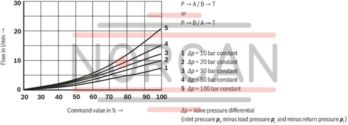
Rated flow 7 l/min at a valve pressure differential of 10 bar
NG6
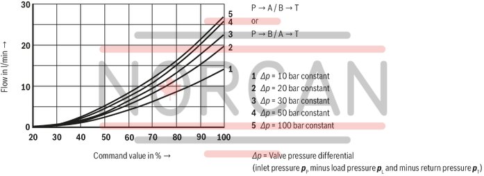
Rated flow 15 l/min at a valve pressure differential of 10 bar
NG6
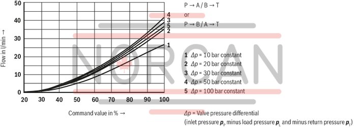
Rated flow 30 l/min at a valve pressure differential of 10 bar
NG6
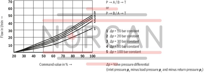
Rated flow 30 l/min at a valve pressure differential of 10 bar
NG10
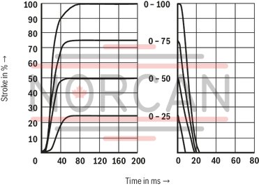
Transition function with stepped electric input signals
NG6
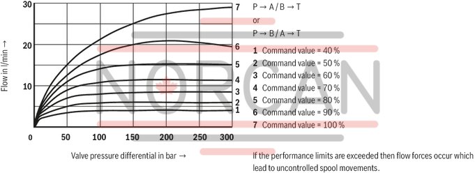
Performance limit rated flow 7 l/min
NG6
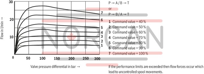
Performance limit rated flow 15 l/min
NG6
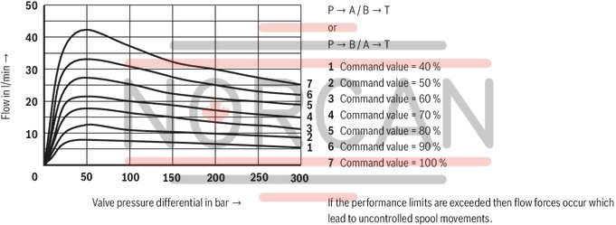
Performance limit rated flow 30 l/min
NG6
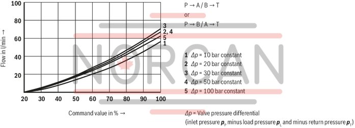
Rated flow 60 l/min at a valve pressure differential of 10 bar
NG10
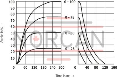
Transition function with stepped electric input signals
NG10
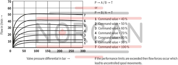
Performance limit rated flow 30 l/min
NG10
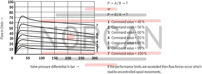
Performance limit rated flow 60 l/min
NG10
Symbols
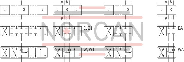
|
With control spool symbol E1- and W1-, the following applies: |
|
|
P → A: qvmax |
B → T: qv/2 |
|
P → B: qv/2 |
A → T: qvmax |
|
Notice: |
|
Type 4WRA
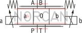
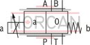
Type 4WRA...EA;Type 4WRA...WA
Connection at connector

Connection at mating connector

4WRA 6
Dimensions in mm

|
1 |
Valve housing |
|
2 |
Proportional solenoid "a" |
|
3 |
Proportional solenoid "b" |
|
4.1 |
Mating connector "A", color gray, separate order |
|
4.2 |
Mating connector "B", color black, separate order |
|
5 |
Name plate |
|
6 |
Identical seal rings for ports A, B, P, and T |
|
7 |
Plug screw for valves with one solenoid (2 spool positions, version "EA" or "WA") |
|
8 |
Space required to remove the mating connector |
|
9 |
Machined valve contact surface; Porting pattern according to ISO 4401-03-02-0-05 (with locating hole) |
Recommended valve mounting screws (separate order):
4 hexagon socket head cap screws ISO 4762 - M5 x 50 - 10.9-flZn-240h-L
tightening torque MA = 7 Nm ± 10%, material no. R913000064 or
4 hexagon socket head cap screws ISO 4762 - M5 x 50 - 10.9
tightening torque MA = 8.9 Nm ± 10%
4WRA 10
Dimensions in mm
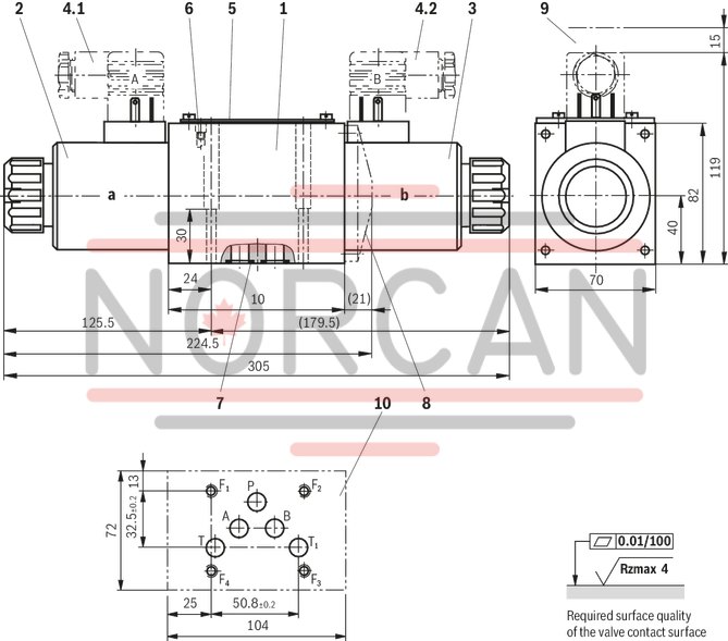
|
1 |
Valve housing |
|
2 |
Proportional solenoid "a" |
|
3 |
Proportional solenoid "b" |
|
4.1 |
Mating connector "A", color gray, separate order |
|
4.2 |
Mating connector "B", color black, separate order |
|
5 |
Name plate |
|
6 |
Valve bleed screw: Notice: Valves are bled prior to delivery |
|
7 |
Identical seal rings for ports A, B, P and T (T1) |
|
8 |
Cover for valves with one solenoid (2 spool positions, version "EA" or "WA") |
|
9 |
Space required to remove the mating connector |
|
10 |
Machined valve contact surface; Porting pattern according to ISO 4401-05-04-0-05 |
Recommended valve mounting screws (separate order):
4 hexagon socket head cap screws ISO 4762 - M6 x 40 - 10.9-flZn-240h-L
tightening torque MA = 12.5 Nm ± 10 %, material no. R913000058 or
4 hexagon socket head cap screws ISO 4762 - M6 x 40 - 10.9
tightening torque MA = 15.5 Nm ± 10%
Mating connectors for valves with connector “K4”, without circuitry, standard
3P Z4
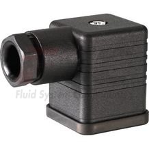
Mating connectors for valves with connector “K4”, without circuitry, standard
3P Z4
For valves with connector “K4” according to EN 175301-803 and ISO 4400, 2-pole + PE, “large cubic connector” Mating connectors for valves with one or two solenoids (individual connection)Data sheet
Spare parts & repair