


BOSCH REXROTH
R900972963
- BOSCH REXROTH
- Material:R900972963
- Model:SFA50F1-1X/M/01
Quantity in stock: 0
The Bosch Rexroth SFA50F1-1X/M/01 (R900972963) is a high-quality pilot-operated check valve designed for both threaded and flange connections, catering to a wide range of hydraulic applications. This particular model is part of the SF series, with the option to select from types SFAGTXM without predecompression and SFAFTXM with predecompression, depending on the specific requirements of the system it will be integrated into. This valve is engineered for direct attachment to working cylinders, offering enhanced control over the flow and movement within hydraulic systems. The inclusion of an integrated high-pressure port expands its capabilities, allowing for a more versatile application in various hydraulic circuits. With its robust design, it ensures reliable operation even under demanding conditions. The Bosch Rexroth SFA50F1-1X/M/01 check valve boasts a size component series X, which indicates its adaptability to different system sizes and configurations. It can handle a maximum operating pressure of up to several hundred bar and supports maximum flow rates measured in liters per minute, which makes it suitable for a broad spectrum of industrial applications where precise fluid control is essential. Manufactured by Bosch Rexroth, a leader in drive and control technologies, this valve exemplifies the company's commitment to quality and performance. Its construction allows for seamless integration into existing hydraulic systems or as part of new installations where reliable backflow prevention is necessary. Whether used with or without predecompression, this model provides an efficient solution for maintaining directional stability and safety in hydraulic circuits.

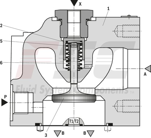
Type SFA…GT0-1X/M/01 (without pre-decompression)
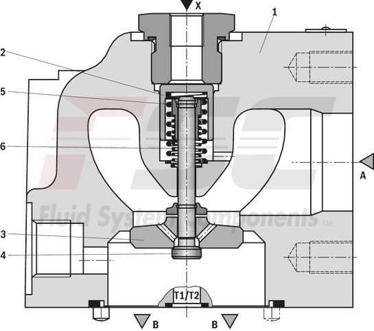
Type SFA…FT1-X/M/01 (with pre-decompression)
|
01 |
Prefill valves |
SFA |
|
02 |
Size 25 |
25 |
|
Size 32 |
32 |
|
|
Size 40 |
40 |
|
|
Size 50 |
50 |
|
|
Size 63 |
63 |
|
|
Size 80 |
80 |
|
|
03 |
Threaded connection (only NG25 and 32) |
G |
|
Flange connection (from NG40) |
F |
|
|
04 |
Without tank bore |
no code |
|
With tank bore (from NG32) |
T |
|
|
05 |
With pre-decompression (from NG32) |
1 |
|
Without pre-decompression |
0 |
|
|
06 |
Component series 10 ... 19 (10 ... 19: unchanged installation and connection dimensions) |
1X |
|
Seal material |
||
|
07 |
NBR seals |
M |
|
Observe compatibility of seals with hydraulic fluid used. (Other seals upon request) |
||
|
Connection version |
||
|
08 |
Threaded holes with pipe thread according to DIN 3852 part 2 |
01 |
|
09 |
Further details in the plain text |
* |
|
01 |
02 |
03 |
04 |
05 |
06 |
07 |
08 |
09 |
|||
|
SFA |
– |
/ |
M |
/ |
01 |
* |
general
|
Nenngröße |
25 | 32 | 40 | 50 | 63 | 80 | |
|
Weight (approx.) |
kg |
4.5 | 6 | 7 | 10.5 | 16 | 23 |
|
Installation position |
any | ||||||
|
Ambient temperature range |
°C |
-30 … +80 | |||||
hydraulic
|
Size |
25 | 32 | 40 | 50 | 63 | 80 | ||
|
Maximum operating pressure |
Port P |
bar |
350 | |||||
|
Anschluss A |
bar |
16 | ||||||
|
Port B |
bar |
350 | ||||||
|
Anschluss X |
bar |
150 | ||||||
|
Cracking pressure 1) |
bar |
≈ 0.12 | ||||||
|
Maximum flow 2) |
Case of application 1 |
l/min |
125 | 200 | 300 | 500 | 800 | 1200 |
|
Case of application 2 |
l/min |
90 | 170 | 250 | 400 | 650 | 1000 | |
|
Case of application 3 |
l/min |
60 | 140 | 220 | 360 | 560 | 900 | |
|
Case of application 4 |
l/min |
40 | 100 | 150 | 240 | 380 | 620 | |
|
Case of application 5 |
l/min |
20 | 70 | 110 | 170 | 280 | 450 | |
|
Druckflüssigkeit |
see table | |||||||
|
Hydraulic fluid temperature range 3) |
°C |
-30 … +80 | ||||||
|
Viscosity range |
mm²/s |
10 … 800 | ||||||
|
Maximum admissible degree of contamination of the hydraulic fluid 4) |
Class 20/18/15 according to ISO 4406 (c) | |||||||
| 1) | Pressure differential at the main poppet for overcoming the spring force |
| 2) | A to B |
| 3) | At the valve working ports |
| 4) | The cleanliness classes specified for the components must be adhered to in hydraulic systems. Effective filtration prevents faults and simultaneously increases the life cycle of the components. For the selection of the filters, see www.boschrexroth.com/filter. |
|
Hydraulic fluid |
Classification |
Suitable sealing materials |
Standards |
|
|
Mineral oils and related hydrocarbons |
HL, HLP, HVLP |
NBR, FKM 3) |
DIN 51524 |
|
|
Bio-degradable |
Insoluble in water |
HETG |
NBR, FKM 3) |
VDMA 24568 |
|
HEES |
FKM 3) |
|||
|
Soluble in water |
HEPG |
FKM 3) |
VDMA 24568 |
|
|
Flame-resistant |
Water-free |
HFDU, HFDR |
FKM 3) |
ISO 12922 |
|
HFC |
NBR |
ISO 12922 |
||
Important information on hydraulic fluids!Flame-resistant and bio-degradable: |
||||
| 3) Upon request |
Flow ‒ case of application 1 (A to B)
Flow ‒ case of application 2 (A to B)
Flow ‒ case of application 3 (A to B)
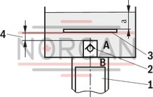
Size of the filling tank at least 1.5 x cylinder content
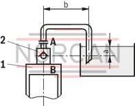
Flow ‒ case of application 4 (A to B)
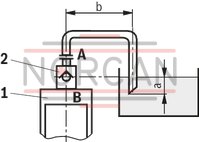
Flow ‒ case of application 5 (A to B)
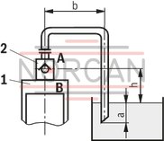
Information on case of application 2 to 5
For limit areas, please contact us. It is often enough, to select a pipeline which is one size larger.
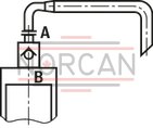
Attention!
An underdimensioned prefill valve and/or an underdimensioned line leads to gas leaks from the hydraulic fluid with corresponding consequences and often to long-term damage at the cylinder seals.
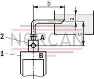
|
1 |
Cylinders |
|
2 |
Prefill valve |
|
3 |
This sheet is not included in the scope of delivery. With smaller tank dimensions and minimum hydraulic fluid level (a), it prevents the formation of tunnels. |
|
4 |
Observe the supply cross-section ‑ differs depending on the size! |
|
a |
min. 300 mm with extended cylinder |
|
b |
max. 1000 mm with the specified maximum flows |
|
c |
≥ 500 mm |
|
h |
~ 300 mm to max. 500 mm |
For applications outside these parameters, please consult us!
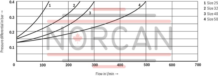
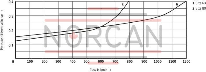
(measured with HLP46, ϑOil = 40 ±5 °C)
Size 25 … 50
Pressure differential Δp between ports A and B dependent on the flow qV in suction direction A to B.
Size 63 and 80
Pressure differential Δp between ports A and B dependent on the flow qV in suction direction A to B.
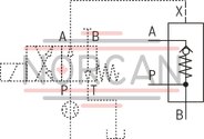
Type SFA… (from NG25)
Type SFA…T… (from NG32)
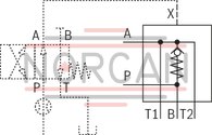
Notice!
Possible circuit with directional valve and nozzle in channel P for one individual prefill valve. For the parallel connection of prefill valves, the nozzle is to be individually provided for every control line!
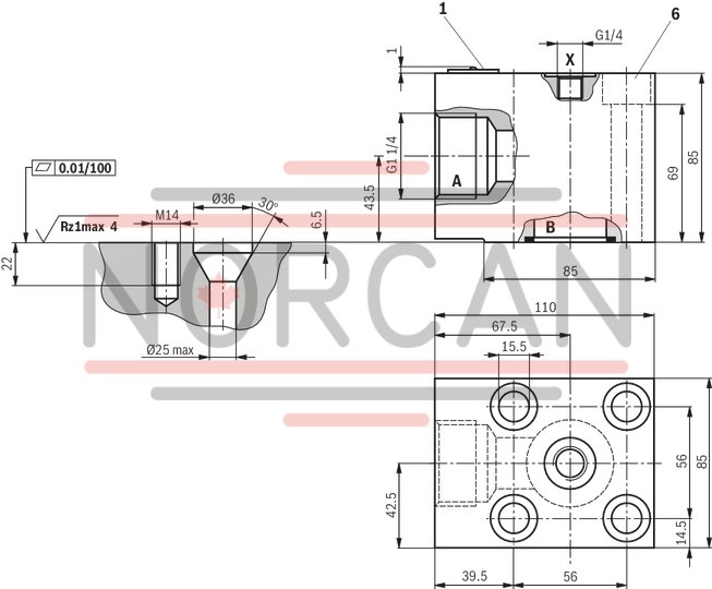
Threaded connection
Dimensions in mm
|
1 |
Name plate |
|
6 |
4 valve mounting bores |
Threaded connection
Dimensions in mm
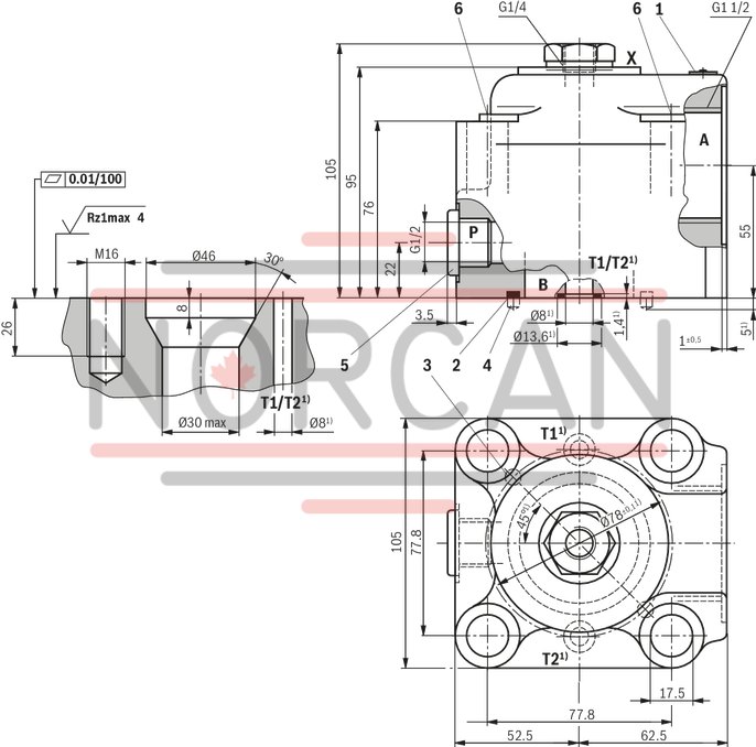
| 1) | Only version "T" |
|
1 |
Name plate |
|
2 |
Seal ring |
|
3 |
Provide bore Ø6.5 x 6 deep for the valve centering in the connection surface! |
|
4 |
2 grooved dowel pins 6 x 12 |
|
5 |
Plug screw |
|
6 |
4 valve mounting bores |
Flange connection
Dimensions in mm
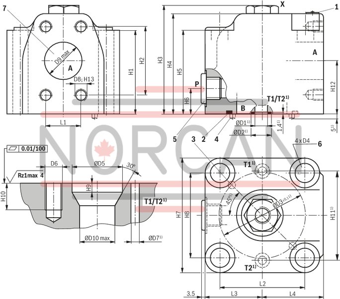
| 1) | Only version "T" |
|
1 |
Name plate |
|
2 |
Seal ring |
|
3 |
Provide bore Ø6.5 x 6 deep for the valve centering in the connection surface! |
|
4 |
2 grooved dowel pins 6 x 12 |
|
5 |
Plug screw (only version "T") |
|
6 |
4 valve mounting bores |
|
7 |
Flange connection according to ISO 6162-1 |
Dimensions
|
NG |
L1 |
L2 |
L3 |
L4 |
ØD1 |
ØD2 |
ØD3 |
ØD4 |
ØD5 |
D6 |
ØD7 |
D8 |
D9 |
ØD10 |
H1 |
H2 |
H3 |
H4 |
H5 |
H6 |
H7 |
H8 |
H9 |
H10 |
H11 |
H12 |
H13 |
||||||
|
max. |
max. |
||||||||||||||||||||||||||||||||
|
mm |
mm |
mm |
mm |
mm |
mm |
mm |
mm |
mm |
mm |
mm |
mm |
mm |
mm |
mm |
mm |
mm |
mm |
mm |
mm |
mm |
mm |
mm |
mm |
mm |
mm |
mm |
mm |
mm |
mm |
||||
| 25 | - | - | - | - | - | - | - | - | - | - | - | - | - | - | - | - | - | - | - | - | - | - | - | - | - | - | - | - | - | - | - | - | |
| 32 | - | - | - | - | - | - | - | - | - | - | - | - | - | - | - | - | - | - | - | - | - | - | - | - | - | - | - | - | - | - | - | - | |
| 40 | 35.7 | 35.7 | 88.4 | ± 0.2 mm | 58 | 62 | 10 | 15.7 | 90 | ± 0.1 | 17.5 | 58 | M16 | 10 | M12 | 38 | 40 | 85 | 69.9 | ± 0.2 | 109 | 102 | 85 | 22 | 116 | 88.4 | ± 0.2 | 10 | 26 | 92 | ± 0.1 | 54 | 18 |
| 50 | 42.9 | 42.9 | 102.5 | ± 0.2 mm | 70 | 72 | 13 | 19 | 104 | ± 0.1 | 22 | 71 | M20 | 13 | M12 | 51 | 50 | 101 | 77.8 | ± 0.2 | 132 | 124 | 101 | 22 | 141 | 102.5 | ± 0.2 | 12 | 32 | 108 | ± 0.1 | 66 | 18 |
| 63 | 50.8 | 50.8 | 113.15 | ± 0.2 mm | 80 | 82 | 13 | 19 | 120 | ± 0.1 | 26 | 90 | M24 | 13 | M12 | 64 | 63 | 125 | 88.9 | ± 0.2 | 152 | 144 | 125 | 30 | 160 | 113.15 | ± 0.2 | 14 | 38 | 130 | ± 0.1 | 83 | 18 |
| 80 | 61.9 | 61.9 | 134 | + 0.3 mm | 92 | 95 | 13 | 19 | 140 | ± 0.1 | 30 | 107 | M27 | 13 | M16 | 76 | 78.5 | 140 | 106.4 | ± 0.2 | 170 | 158 | 140 | 30 | 185 | 134 | + 0.3 | 16 | 43 | 150 | ± 0.1 | 90 | 21 |
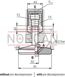
Poppet geometry and determination of the minimum pilot pressure
Dimensions in mm
|
A1 |
Effective area of the main poppet |
|
A2 |
Effective area of the pilot poppet |
|
A3 |
Effective area of the control spool |
|
s1 |
Stroke of the main poppet |
|
s2 |
Stroke of the control spool |
|
F1 |
Spring force of the valve spring |
|
F2 |
Spring force of the compression spring of the control spool |
|
Vst x |
Pilot volume for opening the valve |
|
pÖ |
Cracking pressure (pressure differential at the main poppet for overcoming the spring force F1) |
|
pSt |
Pilot pressure at port X |
|
pB |
System pressure at port B |

|
Example: Type SFA32...G0
pB = 30 bar [435 psi];
pSt = 4.0 x 30 bar [435 psi] = 120 bar [1750 psi]
|
NG |
A1 |
A2 |
A3 |
s1 |
s2 |
F1 |
F2 |
VstX |
Unchecking ratio |
|
|
cm² |
cm² |
cm² |
mm |
mm |
N |
N |
cm³ |
Without pre-decompression 2) |
With pre-decompression |
|
| 25 | 5.31 | - | 1.33 | 6.2 | 5 | 6 … 14 | 38 … 70 | 0.66 | 4 | - |
| 32 | 8.04 | 0.5 1) | 2.01 | 8.5 | 6.5 | 9 … 22 | 58 … 109 | 1.3 | 4 | 0.3 3) |
| 40 | 13.52 | 0.78 1) | 3.14 | 10 | 7 | 14 … 29 | 93 … 162 | 2.2 | 4.3 | 0.3 3) |
| 50 | 21.24 | 1.13 1) | 4.71 | 12.5 | 9 | 23 … 49 | 149 … 261 | 4.2 | 4.5 | 0.3 3) |
| 63 | 32.67 | 1.17 1) | 7.07 | 14.5 | 11 | 35 … 63 | 206 … 348 | 7.8 | 4.6 | 0.3 3) |
| 80 | 49.02 | 2.54 1) | 10.18 | 17 | 13 | 57 … 127 | 310 … 579 | 13.2 | 4.8 | 0.3 3) |
| 1) | Is omitted for version "without pre-decompression" (SFA...0...) |
| 2) | Without pre-decompression |
| 3) | With pre-decompression |
|
Nozzle insert |
Size |
25 | 32 | 40 | 50 | 63 | 80 | |
|
Nozzle Ø in mm |
mm |
0.8 | 1 | |||||