
BOSCH REXROTH
R901057913
$225.52 USD
- BOSCH REXROTH
- Material:R901057913
- Model:ABZMS-35-1X/120F050S-K24
Quantity in stock: 0
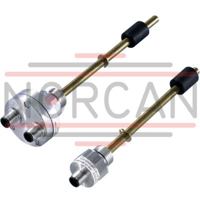
The Bosch Rexroth ABZMS-35-1X/120F050S-K24 (R901057913) is a sophisticated float switch designed to monitor and manage fluid levels within hydraulic systems. This device is adept at controlling tank fluid levels in small power units of types ABSKG...NG; 10, 20, and 30. It features two switching contacts with pre-set switching points at specified millimeters, ensuring precise operation and reliability. The ABZMS-35-1X/120F050S-K24 float switch operates with a maximum pressure tolerance and includes an electrical connector with a Connector pole, Mx, A-coded design for seamless integration into existing systems. The product has a specific length and offers an electrical connection that supports a supply voltage range from 8 to 70 V DC. Its weight is carefully calibrated to ensure proper buoyancy and operation. Equipped with two output signals, the switch can handle various hydraulic fluids including HLP, HFAE, HFC, HFDR, HFDU, HETG, HEES, and HEPG. The device's functionality relies on the movement of the float which contains permanent magnets that activate reed contacts—normally closed and normally open—when reaching certain levels during fluid level changes. Additionally, this model can be equipped with temperature contacts as an option for monitoring maximum hydraulic fluid temperature. However, it's important to note that this feature is intended for shutdown functions rather than continuous temperature control. In summary, the Bosch Rexroth ABZMS-35-1X/120F050S-K24 float switch is a reliable component for hydraulic systems requiring precise fluid level management and offers added functionality with its optional temperature monitoring capability.
Float switch
Unpacked Weight: 0.06461 kg
Float switches are switching devices operated by a float moved by fluid. They are used to control the tank fluid levels in small power units type ABSKG ... NG10; 20; 40 and 60.
The sliding tubes contain two fixedly set reed contacts (normally closed contact and normally open contact) that are switched by the permanent magnets installed in the float.
Fixedly set temperature contacts (option) are fitted to monitor the max. hydraulic fluid temperature.
Function of level switch
When the float reaches the switching points while the oil level is falling, the contacts are operated magnetically. The switching positions of the contacts are maintained until the float passes the switching points again due to a rising oil level.
Switching point L1 is a normally closed contact, the contact function of switching point L2 is optionally a normally closed or normally open contact.
Level switch function
When the float reaches the switching points while the oil level is falling, the contacts are operated magnetically. The switching positions of the contacts are maintained until the float passes the switching points again due to a rising oil level.
Switching point L1 is a normally closed contact, the contact function of switching point L2 is optionally a normally closed or normally open contact.
Temperature contact function
A bimetal plate, which is influenced by temperature, switches when a firmly set response temperature is reached. The temperature contact is not suitable for temperature controlling, but merely for a shutdown function.
| Float switches are switching devices operated by a float moved by fluid. |
| Two switching contacts |
| 1. Switching point prescribed at 120 mm |
| 2nd switching points prescribed at 50 mm |
| Data Sheet | Download Data Sheet |
| 3D CAD | Download 3D CAD |
| Max. pressure | 1 |
| Electrical connection description | Connector, 4-pole, M12 x 1, coding A according to EN 61076-2-101 |
| Productgroup ID | 9,10,11,12,13,14 |
| Length | 50 |
| Display | no |
| Connection diagram | M20 x 1.5 |
| Supply voltage | 10...50 VDC |
| Weight | 0.06461 |
| Output signal | 2 switching outputs |
| Hydraulic fluid | HLP,HFA-E,HFC,HFD-R,HFD-U,HETG,HEES,HEPG |
Ordering code
|
01 |
02 |
03 |
04 |
05 |
06 |
07 |
08 |
09 |
10 |
|||||
|
ABZM |
S |
‒ |
35 |
‒ |
1X |
/ |
F |
‒ |
‒ |
V |
|
Power unit accessories |
||
|
01 |
Measuring devices |
ABZM |
|
02 |
Float switches |
S |
|
03 |
Version |
35 |
|
04 |
Component series 10 ... 19 (10 ... 19: unchanged installation and connection dimensions) |
1X |
|
Minimum contact |
||
|
05 |
Switching point L1 in mm |
… |
|
06 |
Normally closed contact |
F |
|
Maximum contact |
||
|
07 |
Switching point L2 in mm |
… |
|
08 |
Normally closed contact |
F |
|
Normally open contact |
S |
|
|
Temperature contact |
||
|
09 |
Without switching contact |
no code |
|
Switching contact normally closed contact at 63 °C |
T63F1) |
|
|
Switching contact normally closed contact at 70 °C |
T70F |
|
|
Switching contact normally closed contact at 80 °C |
T80F1) |
|
|
Electrical connection 2) |
||
|
10 |
Connector, 4-pole M12 x 1 |
K24 |
|
Connector 4-pole (3 + PE) DIN EN 175301-803 (float switch without temperature contact) |
K14 |
|
|
Connector 7-pole (6 + PE) DIN EN 175201-804 (float switch without temperature contact) |
K6 |
|
| 1) | Only upon request |
| 2) | The mating connectors are not included in the scope of delivery and must be ordered separately, if required (see R.08006) |
|
Order example: Float switch with connection thread M20 x 1.5, with 2 fixedly set switching contacts, switching point L1 = 90 mm normally closed contact, switching point L2 = 30 mm normally open contact, connector K24 for mating connector Z24 (M12 x 1): |
|
| ABZMS-35-1X/090F030S-K24 |
Resistance
|
Hydraulic fluids |
||||
|
Mineral oils |
Mineral oil |
HLP |
according to DIN 51524 |
Resistant |
|
Flame-resistant hydraulic fluids |
Emulsions |
HFA-E |
according to DIN 24320 |
Not resistant |
|
Water solutions |
HFC |
according to VDMA 24317 |
||
|
Phosphoric acid esters |
HFD-R |
|||
|
Organic esters |
HFD-U |
|||
|
Fast bio-degradable hydraulic fluids |
Triglycerides (rape seed oil) |
HETG |
according to VDMA 24568 |
|
|
Synthetic esters |
HEES |
|||
|
Polyglycols |
HEPG |
|||
electrical
|
Plug-in connection |
4-pole M12 x 1 (material: metal) DIN EN 175301-803/DIN EN 175201-804 |
Reed contacts of the float switches
with connection K24 for mating connector M12 x 1; 4-pole
|
Switching voltage range |
V DC |
10 … 50 |
|
Maximum switching current |
A |
0.5 |
|
Maximum switching power |
W |
10 |
Temperature contacts of the float switches
with connection K24 for mating connector M12 x 1; 4-pole
|
Switching voltage range |
V DC |
10 … 50 |
|
Maximum switching current |
A |
2 |
|
Maximum switching cycles |
10000 | |
|
Response tolerance |
K |
± 4 |
|
Hysteresis range |
K |
2 … 10 |
|
Maximum temperature change velocity |
K/min |
1 |
Reed contacts of the float switches
with connection K14 according to DIN EN 175301-803 / K6 according to DIN EN 175201-804
|
Switching voltage range |
V AC |
10 … 230 |
|
Maximum switching current |
A |
0.5 |
|
Maximum switching power |
10 W; 30 VA |
Temperature contacts of the float switches
with connection K14 according to DIN EN 175301-803 / K6 according to DIN EN 175201-804
|
Switching voltage range |
V AC |
10 … 230 |
|
Maximum switching current |
A |
2 |
|
Maximum switching cycles |
10000 | |
|
Response tolerance |
K |
± 5 |
|
Hysteresis range |
K |
2 … 10 |
|
Maximum temperature change velocity |
K/min |
1 |
For inductive and capacitive loads, protection circuits are to be provided (diode, RC element, varistor).
Assignment to reservoirs
Float switches with min./max. switching points
|
Tank size DN10 and 20 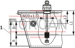
|
Tank size DN40 and 60 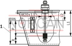
|
|
1 |
Maximum oil level |
|
Float switches ABZMS-35-1X/... |
Tank size DN |
Maximum oil volume |
Capacity fluctuation |
Residual volume |
Switching point |
Switching point |
|
|
P |
R |
L1 |
L2 |
||
|
l |
l |
mm |
mm |
|||
| 090F030S-K24 | 10 | 9.6 l; -; - | 3.8 | 5.8 | 90 | 30 |
| 120F050S-K24 | 20 | 18 l; -; - | 6.8 | 11.2 | 120 | 50 |
| 165F085S-K24 | 40 | 33 l; -; - | 12.2 | 20.8 | 165 | 85 |
| 60 | 54 l; -; - | 17 | 37 | 165 | 85 |
Float switches with min. early warning switching points
|
Tank size DN10 and 20 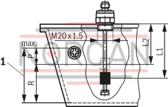
|
Tank size DN40 and 60 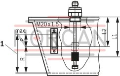
|
|
1 |
Maximum oil level |
|
Float switches ABZMS-35-1X/... |
Tank size DN |
Maximum oil volume |
Capacity fluctuation |
Residual volume |
Switching point |
Switching point |
|
|
P |
R |
L1 |
L2 |
||
|
l |
l |
mm |
mm |
|||
| 090F060S-K24 | 10 | 9.6 l; -; - | 2 | 7.6 | 90 | 60 |
| 120F090S-K24 | 20 | 18 l; -; - | 4 | 14 | 120 | 90 |
| 165F135S-K24 | 40 | 33 l; -; - | 8 | 25 | 165 | 135 |
| 60 | 54 l; -; - | 11 | 43 | 165 | 135 |
For applications outside these parameters, please consult us!
With two switching contacts

With two switching contacts and one temperature contact

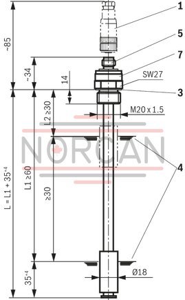
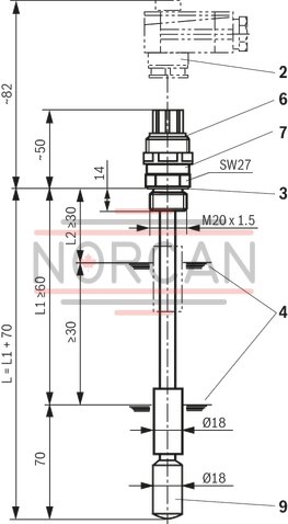
Dimensions: Float switches with two switching contacts
Plug-in connection M12 x 1, max. 50 VDC
Dimensions in mm
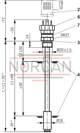
Plug-in connection DIN EN 175301-803, max. 230 VAC
Dimensions in mm
|
1 |
Mating connector for plug-in connections K24 (M12 x 1), see table "Mating connector" |
|
2 |
Mating connector for plug-in connections K14, see table "Mating connector" |
|
3 |
Profile seal M20 x 1.5 RNI 18104 |
|
4 |
Switching point |
|
5 |
Connector K24; 4-pole M12 x 1 |
|
6 |
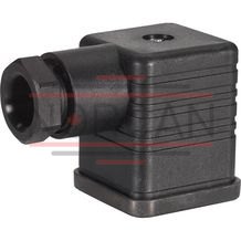
Connector K14; 4-pole (3 + PE) DIN EN 175301-803 |
|
7 |
Name plate |
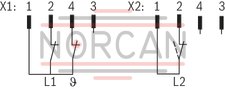
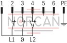
Pinout
|
Switching function with plug-in connection M12 x 1 |
|

|
|
|
Switching function with plug-in connection DIN EN 175301-803 |
|

|
|
|
L1 = |
Normally closed contact at min. |
|
L2 = |
Normally closed or normally open contact as early warning |
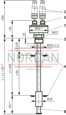
Dimensions: Float switches with two switching contacts and temperature contact
Plug-in connection M12 x 1, max. 50 VDC
Dimensions in mm
Plug-in connection DIN EN 175201-804, max. 230 VAC
Dimensions in mm
|
1 |
2 x mating connector for plug-in connections K24 (M12 x 1), see table "Mating connector" |
|
2 |
Mating connector for plug-in connections K6, see table "Mating connector" |
|
3 |
Profile seal M20 x 1.5 RNI 18104 |
|
4 |
Switching point |
|
5 |
2 x connector K24; 4-pole M12 x 1 |
|
6 |
Connector K6; 7-pole (6 + PE) DIN EN 175201-804 |
|
7 |
Name plate |
|
8 |
Temperature contact in sliding tube |
|
9 |
Temperature contact |
Pinout
|
Switching function with plug-in connection M12 x 1 |
|
|
|
|
Switching function with plug-in connection DIN EN 175201-804 |
|
|
|
|
L1 = |
Normally closed contact at min. |
|
L2 = |
Normally closed or normally open contact as early warning |
|
ϑ = |
Normally closed contact at max. temperature |
Installation information
Vertical installation according to technical data (see “Technical data”) Avoid flows Do not expose the switch to heavy impacts and bends Avoid external magnetic fields. Thus, the function of the reed contacts may be impaired.
Electrical connections:
Electrical connections may only be established by specialists Tighten the round connectors M12 x 1 and/or mating connectors after connection Only plug in the round connectors M12 x 1 and/or mating connectors in the de-energized condition Do not overload the contacts (see “Technical data”) In case of inductive load provide a protection circuit!Normative reference
DIN EN 50020
Electric operating equipment for potentially explosive atmospheres - Intrinsic safety “i”; German version EN 50020:2002
DIN EN 60079-0
Electric operating equipment for potentially explosive gas atmospheres - Part 0: General requirements (IEC 60079-0:2004); German version EN 60079-0:2004
DIN EN 60079-14
Electric operating equipment for potentially explosive gas atmospheres - Part 14: Electric systems for endangered areas (except for mining) (IEC 60079-14:2002); German version EN 60079-14:2003
DIN EN 175201-804
Detail specification - Circular connectors - Round contacts, size diameter 1.6 mm, threaded coupling; German version EN 175201-804:1999
DIN EN 175301-803
Detail specification: Rectangular connectors - Flat contacts, 0,8 mm thickness, locking screw not detachable; German version EN 175301-803:1999
Mating connectors
|
For detailed information see data sheet 08006 |
|||
|
Mating connector for connector K14 according to DIN EN 175301-803 |
Mating connector for connector K6 according to DIN EN 175201-804 |
||
|
Denomination |
Part number |
Denomination |
Part number |
|
LEITUNGSDOSE 4P Z14 M SW SPEZ |
R901017012 |
LEITUNGSDOSE 7P Z6 N6RFFK |
R900002803 |
|
|
|||
|
Mating connector for connector K24 |
Mating connector for connector K24 with potted-in PVC cable, 3 m long |
||
|
Denomination |
Part number |
Denomination |
Part number |
|
LEITUNGSDOSE 4P Z24 SPEZ |
R900031155 |
LEITUNGSDOSE 4P Z24M12X1+3MSPEZ |
R900064381 |
Mating connectors for mechanical pressure switches with connector “K14”, without circuitry, standard
4P Z14
Mating connectors for mechanical pressure switches with connector “K14”, without circuitry, standard
4P Z14
For mechanical pressure switches with connector “K14”, according to EN 175301-803 and ISO 4400, 3-pole + PE, “large cubic connector”Data sheet
Spare parts & repair
Mating connectors for sensors and valves with connector “K24”, “K35” and “K72”, M12 x 1
4P Z24
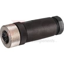
Mating connectors for sensors and valves with connector “K24”, “K35” and “K72”, M12 x 1
4P Z24
For sensors and valves with connector “K24”, “K35” and “K72” Mating connectors M12, 4-pole, line cross-section 0.75 mm2Data sheet
Spare parts & repair
Mating connectors for sensors and valves with connector “K24”, “K35” and “K72”, M12 x 1, with assembled connection line
4P Z24 +
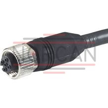
Mating connectors for sensors and valves with connector “K24”, “K35” and “K72”, M12 x 1, with assembled connection line
4P Z24 +
For sensors and valves with connector “K24”, “K35” and “K72” Mating connectors M12, 4-pole, line cross-section 0.75 mm2Data sheet
Spare parts & repair
Mating connectors for mechanical position switches, mechanical pressure switches and valves with central connection with connector “K6” and “DK6L”, 6-pole + PE
7P Z6
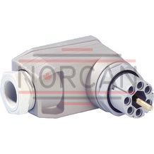
Mating connectors for mechanical position switches, mechanical pressure switches and valves with central connection with connector “K6” and “DK6L”, 6-pole + PE
7P Z6
Mating connectors for mechanical position switches, mechanical pressure switches and valves with central connection with connector “K6”Data sheet
Spare parts & repair
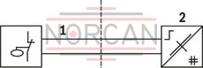
Use in potentially explosive atmospheres according to Directive 94/9/EC (ATEX)
According to DIN EN 50020 float switches are simple electrical apparatus, which are not provided with voltage sources.
The electrical components consist of reed contacts, bimetal thermostats, plug-in connections and terminals.
The equipment complies with construction regulations according to DIN EN 60079-0 and DIN EN 50020.
According to DIN EN 60079-14 these simple, electrical apparatus may be used in intrinsically safe electric circuits [EEx ib] in systems for equipment class II, category 2G (Zone 1) and category 3G (Zone 2) without marking and certification.
The apparatus are assigned to category ib and temperature class T6.
|
Intrinsically safe, electrical equipment in potentially explosive atmosphere(zone 1 and 2) |
Associated electrical equipment in safe zone |
|
|
||
|
1 |
Cable |
|
2 |
Isolating relay |