


BOSCH REXROTH
R901070103
$256.25 USD
- BOSCH REXROTH
- Material:R901070103
- Model:KKDER1CA/HN9V
Quantity in stock: 0
The Bosch Rexroth KKDER1CA/HN9V (R901070103) is a high-performance directional spool valve, designed for direct operation with solenoid actuation. This screw-in cartridge valve is part of the product family classification of direct operated directional spool valves and falls under the product group ID of KKDE. The valve boasts a maximum operating pressure of up to 350 bar and can handle a maximum flow rate that ensures efficient performance in various hydraulic applications. Featuring a Sun TA cavity, the KKDER1CA/HN9V valve is compatible with multiple hydraulic fluids including HL, HLP, HLPD, HVLP, HVLPD, HEES, HEPR, HEPG, HFDU, HFDR, and HFAS. It is equipped with wet-pin DC solenoids that ensure reliable actuation of the control spool. The manual override feature is concealed but allows for manual operation of the valve if necessary. The valve's construction includes a housing with a movable socket and a control spool which are both essential for its function. A return spring maintains the control spool in its initial position when de-energized. The main ports can sustain continuous operating pressure allowing for flow in both directions as per user requirements. This model has been engineered to provide precise control over the start, stop, and direction of flow in hydraulic systems. It features an integrated coil that must be ordered separately and has a nominal flow rate for efficient operation. The poppet-type spool within this component series A size valve ensures smooth operation and longevity. Overall, the Bosch Rexroth KKDER1CA/HN9V offers robust performance for industrial applications requiring precise hydraulic control with its direct-acting design and versatile compatibility with various fluid types.
3/2 directional spool valve, direct operated with solenoid actuation
Unpacked Weight: 0.3138 kg
Version "K4" (with mating connector)
Type KKDER1CA/HN9V

Version "C4"
General information
The 3/2 directional spool valves are direct operated, pressure-compensated screw-in cartridge valves. They control the start, stop and direction of flow and basically consist of a housing (1) with moveable socket (2), a control spool (5) and a return spring (4).
Function
In the de-energized condition, the control spool (5) is held in the initial position by the return spring (4). The control spool (5) is actuated by wet-pin DC solenoids (3). The symbols are realized by different spools (C or U). The main ports ➀, ➁ and ➂ can be loaded continuously with an operating pressure of 350 bar and the flow can be directed into both directions (see Symbols).
The manual override (6) allows for the switching of the valve without solenoid energization. It is also available in screwable version"N10" (7) (see Type keys).
| Screw-in cartridge valve |
| Maximum operating pressure 350 bar (5000 psi) |
| Maximum flow 60 l/min (16 gpm) |
| Cavity Sun T-11A |
| Max. pressure | 350 |
| Coil | GZ37 |
| Product family classification | 3/2 directional spool valve, direct operated with solenoid actuation |
| Productgroup ID | 9,10,11,12,13,14 |
| Product family type | KKDE |
| Ports number | 3 |
| Manual override | Concealed manual override |
| Type of actuation | Solenoid-actuated on/off |
| Sealing material | FKM |
| Cavity | Sun T-11A |
| Product type | KKDE |
| Max. flow | 60 |
| Type of connection | Screw-in cartridge valve |
| Nominal flow | 60 |
| Direct - Pilot | Direct acting |
| Positions | 2 |
| Product family | 3 ways |
| Coil integrated | To be ordered separately |
| Spool Poppet | Spool type |
| Weight | 0.3138 |
| Hydraulic fluid | HL,HLP,HLPD,HVLP,HVLPD,HEES,HEPR,HEPG,HFDU,HFDR,HFAS |
(valve without coil)1)
|
01 |
02 |
03 |
04 |
05 |
06 |
07 |
08 |
09 |
|
|
KKDE |
R |
1 |
A |
/ |
H |
V |
* |
|
01 |
Directional spool valve, direct operated, electrically operated |
KKDE |
|
|
02 |
Maximum operating pressure 350 bar |
R |
|
|
03 |
Size |
1 |
|
|
04 |
3 main ports |
||
|
Symbols 2) |

|

|
C |

|

|
U |
|
|
05 |
Component series |
A |
|
|
06 |
High Performance and mounting cavity R/T-11A (see mounting cavity) |
H |
|
|
07 |
Without manual override |
N0 |
|
|
With concealed manual override 3) |
N9 |
||
|
Seal material |
|||
|
08 |
FKM seals (other seals upon request) Observe compatibility of seals with hydraulic fluid used. |
V |
|
|
09 |
Further details in the plain text |
* |
|
| 1) Complete valves with mounted coil on request. | |
| 3) Screwable manual override “N10” possible (material no. R901051231, separate order) |
general
|
Size |
1 | ||
|
Installation position |
any | ||
|
Ambient temperature range |
°C |
-40 … +110 | |
|
Weight |
Valve |
kg |
0.3 |
|
Coil |
kg |
0.25 | |
hydraulic
|
Size |
1 | |
|
Maximum operating pressure 1) |
bar |
350 |
|
Maximum flow |
l/min |
60 |
|
Hydraulic fluid |
see table | |
|
Hydraulic fluid temperature range |
°C |
-40 … +80 |
|
Viscosity range |
mm²/s |
4 … 500 |
|
Maximum admissible degree of contamination of the hydraulic fluid 2) |
Class 20/18/15 according to ISO 4406 (c) | |
|
Fatigue strength according to ISO 10771 |
10 million (at 350 bar) | |
| 1) | At all ports |
| 2) | The cleanliness classes specified for the components must be adhered to in hydraulic systems. Effective filtration prevents faults and simultaneously increases the life cycle of the components. For the selection of the filters, see www.boschrexroth.com/filter. |
|
Hydraulic fluid |
Classification |
Suitable sealing materials |
Standards |
|
|
Mineral oils and related hydrocarbons |
HL, HLP, HLPD, HVLP, HVLPD |
FKM |
DIN 51524 |
|
|
Environmentally compatible |
Insoluble in water |
HEES |
FKM |
ISO 15380 |
|
HEPR |
FKM |
|||
|
Soluble in water |
HEPG |
FKM |
ISO 15380 |
|
|
Containing water |
Water-free |
HFDU, HFDR |
FKM |
ISO 12922 |
|
Containing water |
HFAS |
FKM |
ISO 12922 |
|
|
Important information on hydraulic fluids! For further information and data on the use of other hydraulic fluids, please refer to data sheet 90220 or contact us! There may be limitations regarding the technical valve data (temperature, pressure range, life cycle, maintenance intervals, etc.)! The flash point of the process and operating medium used must be 40 K over the maximum solenoid surface temperature. Flame-resistant – containing water: The maximum pressure differential per control edge is 175 bar. Otherwise, there is increased cavitation erosion.Tank preloading < 1 bar or > 20% of the pressure differential. The pressure peaks should not exceed the maximum operating pressures! Environmentally compatible: When using environmentally compatible hydraulic fluids that are simultaneously zinc-solving, zinc may accumulate in the medium (700 mgzinc per pole tube). |
||||
electrical
|
Voltage type |
Direct voltage | ||
|
Power supply 1) |
V |
12 24 |
|
|
Voltage tolerance against ambient temperature |
see voltage tolerance characteristic curve | ||
|
Power consumption |
W |
22 | |
|
Duty cycle |
% |
100 | |
|
Maximum coil temperature 2) |
°C |
150 | |
|
Switching time according to ISO 6403 |
ON |
ms |
≤ 80 |
|
OFF |
ms |
≤ 50 | |
|
Maximum switching frequency |
1/h |
15000 | |
|
Protection class according to DIN EN 60529 (VDE 0470-1), DIN 40050-9 |
Version "K4" |
IP65 (with mating connector mounted and locked) | |
|
Version "C4" |
IP66 with mating connector mounted and locked IP69K with Rexroth mating connector (material no. R901022127) |
||
|
Version "K40" |
IP69K with mating connector mounted and locked | ||
| 1) | Other voltages upon request |
| 2) | Due to the surface temperatures of the solenoid coils, the standards ISO 13732-1 and EN 982 need to be adhered to! |
For applications outside these parameters, please consult us!
With the electrical connection "K4", the protective earthing conductor (PE, grounded) is to be connected in accordance with the stipulations.
Voltage tolerance against ambient temperature; duty cycle
Voltage range and duty cycle dependent on the ambient temperature
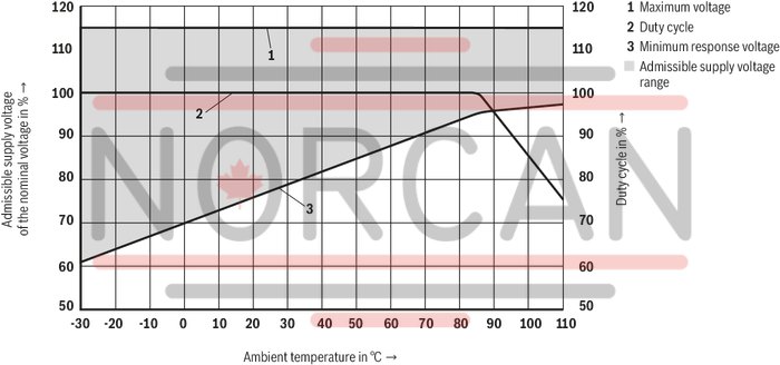
(measured with HLP46, ϑoil = 40 ±5 °C) and 24 V coil
Δp-qV characteristic curves – Symbol C
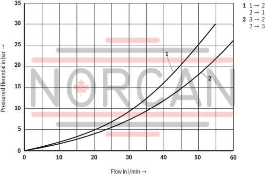
Δp-qV characteristic curves – Symbol U

Performance limits (measured with HLP46, ϑOil = 40 ±5 °C and 24 V coil)
Symbol C
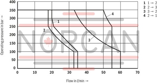
Attention!
The performance limit has been determined with the solenoids at operating temperature and with 10 % undervoltage.
Performance limits (measured with HLP46, ϑOil = 40 ±5 °C and 24 V coil)
Symbol U

Symbol “C”
Symbol “U”
Dimensions in mm

|
1 |
Mating connectors, separate order, see data sheet 08006 |
|
2 |
Space required to remove the mating connector |
|
3 |
Wrench size 24, tightening torque MA = 45 to 50 Nm |
|
4 |
Dimension for mating connector “K4”, without circuitry |
|
5 |
Dimension () for mating connector “K4”, with circuitry |
|
6 |
Version "K40" |
|
7 |
Version "C4" |
|
8 |
Nut, tightening torque MA = 5+1 Nm |
|
9 |
Coil (separate order, see type key) |
|
10 |
Concealed manual override "N9", optional |
|
11 |
Screwable manual override "N10" (separate order, see Type keys) |
|
➀ |
Main port 1 |
|
➁ |
Main port 2 |
|
➂ |
Main port 3 |
|
LS |
Location shoulder |
Mounting cavity R/T-11A; 3 main ports; thread M20 x 1.5 mm
Dimensions in mm

|
➀ |
Main port 1 |
|
➁ |
Main port 2 |
|
➂ |
Main port 3 |
|
LS |
Location shoulder |
|
Tolerance for all angles ± 0.5 ° |
|
Mating connectors for directional valves with connector "C4" and "C4Z" (AMP Junior-Timer), litz wire outer diameter 2.2 mm to 3.0 mm
2P JUNIOR D2 2
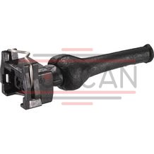
Mating connectors for directional valves with connector "C4" and "C4Z" (AMP Junior-Timer), litz wire outer diameter 2.2 mm to 3.0 mm
2P JUNIOR D2 2
For directional valves with connector "C4" and "C4Z" (AMP Junior-Timer)Data sheet
Spare parts & repair
Mating connectors for directional valves with connector "K40" (Deutsch plug)
2P DT06 K40
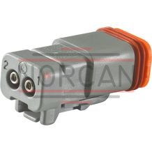
Mating connectors for directional valves with connector "K40" (Deutsch plug)
2P DT06 K40
For directional valves with "K40" connector (Deutsch plug)Data sheet
Spare parts & repair