

BOSCH REXROTH
R901079982
- BOSCH REXROTH
- Material:R901079982
- Model:M-Z4SEH 16 E2X/3CG24ETK4
Due to extremely high demand, please call 877-366-7226 for availability
The Bosch Rexroth M-Z4SEH 16 E2X/3CG24ETK4 (R901079982) is a sophisticated directional seat valve designed for precise control in hydraulic systems. This electrohydraulic actuated valve is part of the MZSEH series and stands out for its versatility, being configurable to switch or shut off flow through one or two channels based on the specific version ordered. The construction of this valve includes a durable housing, a pilot operated check valve installation set, and a pilot control valve, all engineered to ensure leak-free operation whether the valve is open or closed. The M-Z4SEH 16 E2X/3CG24ETK4 operates based on pressure differentials, employing both a compression spring and hydraulic forces to influence the opening and closing of the valve spool. The resulting action from these forces dictates the check valve installation sets' switching positions. Pilot pressure application and unloading are managed by the pilot control valve which draws pilot oil supply from the highest pressure among channels A, B, P, or X with safety ensured by an integrated check valve. This model offers various versions for pilot oil supply and return configurations: Version XY utilizes external channels X and Y for supply and return respectively; Version PY uses internal supply from channel P with external return through Y; Version PT combines internal supply from channel P with internal return via T; Version XT opts for external supply from X with internal return through T. Each version accommodates different system designs while ensuring efficient operation. The M-Z4SEH 16 E2X/3CG24ETK4 also features compatibility with porting patterns according to ISO standards NG6 and NG10. It is equipped with wet-pin DC solenoids that contribute to its reliable actuation. For operational flexibility, it offers optional manual override capabilities as well as different combinations of locking and pass-through functions to suit various application requirements. Electrical connections are made through individual connections ensuring easy integration into existing systems.
Type M-Z4SEH 10 …

General
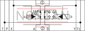
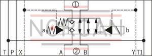
The SEH type directional valves are directional seat valves with electro-hydraulic actuation. Here, depending on the order version, it can be switched or switched off via one or two channels.
The directional valve basically consists of a housing (1), a pilot operated check valve installation set (2), pilot control valve (3) as well as blanking plugs for the pilot oil supply. The valve is free-flowing, independent from the direction, and is opened or blocked in a leakage-free manner depending on the switching position of the pilot control valve and the pressure ratio in the main valve.
Function
The function of the valve is pressure-dependent. The force of the compression spring (4) as well as the force generated by pressure in the control chamber (5) take effect in the closing direction, while the forces generated by pressure in the channels A and B take effect in the opening direction of the valve spool (6) with spool sealing. The direction of action of the resulting force from the opening and closing forces determines the switching position of the check valve installation sets (2). The pilot pressure application and/or unloading is implemented via the pilot control valve (3) depending on the selected pilot oil supply. The pilot oil supply is implemented via the respective highest pressure from the channels A, B, P or X and is secured via a check valve (7).
Notice!
For nozzles and plug fitting, please refer to the project planning information.
|
➀ |
component side |
|
➁ |
plate side |
Version “XY”
The pilot oil supply is implemented externally - via the X channel - from a separate circuit.
The pilot oil return is implemented externally via the Y channel into the tank.
Version “PY”
The pilot oil supply is implementedinternally from the P channel of the main valve.
The pilot oil return is implemented externally via the Y channel into the tank. In the subplate, port X is closed.
Version “PT”
The pilot oil supply is implemented internally from the P channel of the main valve.
The pilot oil return is implemented internally via the T channel into the tank. In the subplate, ports X and Y are closed.
Version “XT”
The pilot oil supply is implemented externally - via channel X - from a separate circuit.
The pilot oil supply is implemented internally - via channel T - into the tank. In the subplate, port Y is closed.
|
Connection |
Internal |
External |
Port in subplate closed |
||
|
Version “XY" |
Pilot oil supply |
X |
– |
✔ |
– |
|
Pilot oil return |
Y |
– |
✔ |
||
|
Version “PY” |
Pilot oil supply |
P |
✔ |
– |
X |
|
Pilot oil return |
Y |
– |
✔ |
||
|
Version “PT” |
Pilot oil supply |
P |
✔ |
– |
X and Y |
|
Pilot oil return |
T |
✔ |
– |
||
|
Version “XT” |
Pilot oil supply |
X |
– |
✔ |
Y |
|
Pilot oil return |
T |
✔ |
– |
||
|
01 |
02 |
03 |
04 |
05 |
06 |
07 |
08 |
09 |
10 |
11 |
12 |
13 |
14 |
15 |
||||
|
M |
– |
Z |
4 |
SEH |
– |
2X |
/ |
3 |
C |
K4 |
/ |
* |
|
01 |
Mineral oil |
M |
|
02 |
Sandwich plate |
Z |
|
03 |
4 main ports |
4 |
|
Type of actuation |
||
|
04 |
electro-hydraulic |
SEH |
|
05 |
Size 10 |
10 |
|
Size 16 |
16 |
|
|
06 |
Symbols |
|

|
E |
|

|
E1 |
|

|
A |
|

|
B |
|
|
07 |
Component series 20 ... 29 (20 ... 29: unchanged installation and connection dimensions) |
2X |
|
Pilot control valve |
||
|
08 |
3/2 directional seat valve, type KSDE |
3 |
|
09 |
Wet-pin DC solenoid with detachable coil |
C |
|
10 |
Direct voltage 24 V |
G24 |
|
Nominal voltage 205 V at DC solenoid with operation with AC voltage mains (AC voltage mains 230 V – 50/60 Hz with an admissible voltage tolerance of +/- 10 %) |
G205 |
|
|
Nominal voltage 96 V at DC solenoid with operation with AC voltage mains (AC voltage mains 110 V - 50/60 Hz with an admissible voltage tolerance of +/- 10 %) |
G96 |
|
|
11 |
Without manual override |
no code |
|
With concealed manual override |
N9 |
|
|
With screwable manual override (actuation by means of knurled screw) |
N11 |
|
|
12 |
External pilot oil supply, external pilot oil return |
XY |
|
Internal pilot oil supply, external pilot oil return |
PY |
|
|
Pilot oil supply internal, pilot oil return internal |
PT |
|
|
External pilot oil supply, internal pilot oil return |
XT |
|
|
For further details, please refer to Pilot oil supply |
||
|
Electrical connection |
||
|
13 |
Without mating connector, individual connection with connector according to DIN EN 175301-803 |
K4 1; 2) |
|
Seal material |
||
|
14 |
NBR seals |
N |
|
FKM seals (other seals upon request) |
F |
|
|
Observe compatibility of seals with hydraulic fluid used. |
||
|
15 |
Further details in the plain text |
* |
| 1) For the connection to the AC voltage mains, a DC solenoid must be used, which is controlled via a rectifier (see AC voltage mains table). | |
| For individual connection, a mating connector with integrated rectifier can be used (separate order). | |
| 2) Mating connectors, separate order. |
|
➀ |
component side |
|
➁ |
plate side |
general
|
Size |
10 | 16 | ||
|
Weight |
kg |
6 | 14 | |
|
Installation position |
any | |||
|
Ambient temperature range |
NBR seals |
°C |
-30 … +80 | |
|
FKM seals |
°C |
-20 … +80 | ||
hydraulic
|
Size |
10 | 16 | ||
|
Maximum operating pressure |
bar |
315 | ||
|
Maximum flow |
l/min |
140 | 300 | |
|
Hydraulic fluid |
see table | |||
|
Hydraulic fluid temperature range |
NBR seals |
°C |
-30 … +80 | |
|
FKM seals |
°C |
-20 … +80 | ||
|
Viscosity range |
mm²/s |
10 … 380 | ||
|
Maximum admissible degree of contamination of the hydraulic fluid 1) |
Class 20/18/15 according to ISO 4406 (c) | |||
| 1) | The cleanliness classes specified for the components must be adhered to in hydraulic systems. Effective filtration prevents faults and simultaneously increases the life cycle of the components. For the selection of the filters, see www.boschrexroth.com/filter. |
|
Hydraulic fluid |
Classification |
Suitable sealing materials |
Standards |
|
|
Mineral oils and related hydrocarbons |
HL, HLP, HLPD |
NBR, FKM |
DIN 51524 |
|
|
Environmentally compatible |
Insoluble in water |
HEES |
NBR, FKM |
ISO 15380 |
|
HEPR |
FKM |
|||
|
Soluble in water |
HEPG |
FKM |
ISO 15380 |
|
|
Containing water |
Water-free |
HFDU, HFDR |
FKM |
ISO 12922 |
|
Containing water |
HFC |
NBR |
||
|
Important information on hydraulic fluids! For further information and data on the use of other hydraulic fluids, please refer to data sheet 90220 or contact us! There may be limitations regarding the technical valve data (temperature, pressure range, life cycle, maintenance intervals, etc.)! Environmentally compatible: When using environmentally compatible hydraulic fluids that are simultaneously zinc-solving, zinc may accumulate in the medium (700 mg zinc per pole tube). |
||||
electrical
|
Voltage type |
Direct voltage | |
|
Available voltages |
V |
24 / 96 / 205 |
|
Power consumption |
W |
22 |
|
Type of protection according to EN 60529 |
IP65 (with mating connector mounted and locked) | |
In the electrical connection, the protective earthing conductor (PE, grounded) is to be connected in accordance with the stipulations.
Notice!
For further technical data regarding the pilot control valve of the KSDE type, please refer to the data sheet.
For applications outside these parameters, please consult us!
(measured with HLP46, ϑOil = 40 ±5 °C)
Δp-qV characteristic curves, size 10

Δp-qV characteristic curves, size 16

|
➀ |
component side |
|
➁ |
plate side |
Pilot oil supply
|
➀ |
component side |
➁ |
plate side |
Version “XY"

Version “PY”

Version “XT”

Version “PT”

Size 10
Size 16
|
Pilot control valve, normally open, symbol “E” |
Pilot control valve, normally closed, symbol “E1” |
|
|
Detailed |

|

|
|
Version “XY" |

|
|
|
Pilot control valve, normally open, symbol “A” |
Pilot control valve, normally closed, symbol “B” |
|
|
Detailed |

|

|
|
Version “XY" |
|

|
Size 10
Size 16
|
Pilot control valve, normally open, symbol “E” |
Pilot control valve, normally closed, symbol “E1” |
|
|
Detailed |

|

|
|
Version “XY" |

|

|
|
Pilot control valve, normally open, symbol “A” |
Pilot control valve, normally closed, symbol “B” |
|
|
Detailed |

|

|
|
Version “XY" |

|

|
Size 10
Dimensions in mm

|
➀ |
Component side – porting pattern according to ISO 4401-05-05-0-05 |
|
➁ |
Plate side – porting pattern according to ISO 4401-05-05-0-05 |
|
1 |
Mating connector without circuitry (separate order) |
|
2 |
Mating connector with circuitry (separate order) |
|
3 |
DC solenoid “a” (mating connector color: gray) |
|
4 |
3/2 directional seat valve, type KSDE |
|
5 |
Name plate |
|
6 |
Identical seal rings for ports A, B, P, T and T1 |
|
7 |
Identical seal rings for ports X and Y |
|
8 |
Space required to remove the mating connector |
|
9 |
Main valve |
|
10 |
Plug screw or check valve, tightening torque M A= 8 Nm |
Subplates according to data sheet 45054 (separate order)
Valve mounting screws (separate order)
4 hexagon socket head cap screws ISO 4762 - M6 - 10.9
Notice!
Length and tightening torque of the valve mounting screws must be calculated in connection with the components mounted underneath and above the sandwich plate valve.
Size 16
Dimensions in mm

|
➀ |
Component side – porting pattern according to ISO 4401-07-07-0-05 |
|
➁ |
Plate side – porting pattern according to ISO 4401-07-07-0-05 |
|
1 |
Mating connector without circuitry (separate order) |
|
2 |
Mating connector with circuitry (separate order) |
|
3 |
DC solenoid “a” (mating connector color: gray) |
|
4 |
3/2 directional seat valve, type KSDE |
|
5 |
Name plate |
|
6 |
Identical seal rings for ports A, B, P, and T |
|
7.1 |
Seal ring for port X |
|
7.2 |
Seal ring for port Y |
|
8 |
Space required to remove the mating connector |
|
9 |
Main valve |
|
10 |
Plug screw or check valve, tightening torque M A= 8 Nm |
|
11 |
Grooved pin |
Valve mounting screws (separate order)
4 hexagon socket head cap screws ISO 4762 - M10 - 10.9
|
Tightening torques MA |
Plugs or check valve (channel A, B, P and X) |
Nm |
8 | 45 |
|
3/2 directional seat valve, type KSDE |
Nm |
45 | ||
|
Mounting screw, coil |
Nm |
4 | ||
|
Plug screw, 2-way cartridge valve |
Nm |
25 | 100 | |
Plug for NG10

Plug for NG16

|
Item |
Version |
Plug screw |
|
|
NG10 |
NG16 |
||
|
1 |
„XY“ |
M4 x 5 |
M6 |
|
3 |
M6 |
M6 |
|
|
2 |
„PY“ |
M6 |
M8 x 1 |
|
3 |
M6 |
M6 |
|
|
1 |
„PT“ |
M4 x 5 |
M6 |
|
4 |
M6 |
M6 |
|
|
2 |
„XT“ |
M6 |
M8 x 1 |
|
4 |
M6 |
M6 |
|
Mating connectors for valves with connector “K4”, without circuitry, standard
3P Z4
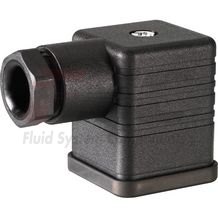
Mating connectors for valves with connector “K4”, without circuitry, standard
3P Z4
For valves with connector “K4” according to EN 175301-803 and ISO 4400, 2-pole + PE, “large cubic connector” Mating connectors for valves with one or two solenoids (individual connection)Data sheet
Spare parts & repair
Mating connectors for valves with connector “K4”, with indicator light
3P Z5L
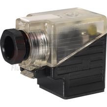
Mating connectors for valves with connector “K4”, with indicator light
3P Z5L
For valves with connector “K4” according to EN 175301-803 and ISO 4400, 2-pole + PE, “large cubic connector” Mating connectors for valves with one or two solenoids (individual connection)Data sheet
Spare parts & repair
Mating connectors for valves with connector “K4”, with indicator light and Zener diode suppression circuit
3P Z5L1
Mating connectors for valves with connector “K4”, with indicator light and Zener diode suppression circuit
3P Z5L1
For valves with connector “K4” according to EN 175301-803 and ISO 4400, 2-pole + PE, “large cubic connector” Mating connectors for valves with one or two solenoids (individual connection)Data sheet
Spare parts & repair
Mating connectors for valves with connector “K4”, with rectifier
3P RZ5
Mating connectors for valves with connector “K4”, with rectifier
3P RZ5
For valves with connector “K4” according to EN 175301-803 and ISO 4400, 2-pole + PE, “large cubic connector” Mating connectors for valves with one or two solenoids (individual connection)Data sheet
Spare parts & repair