


BOSCH REXROTH
R901108034
- BOSCH REXROTH
- Material:R901108034
- Model:4WPZ6D6X/OF/ZV
Quantity in stock: 0
The Bosch Rexroth 4WPZ6D6X/OF/ZV (R901108034) is a high-performance directional spool valve designed to manage the start, stop, and direction of fluid flow in hydraulic systems. This valve is characterized by its robust housing, pneumatic actuation cylinder(s), control spool, and return spring(s). The axial positioning of the control ports facilitates seamless integration into various hydraulic circuits. When de-energized, the control spool maintains its central or initial position courtesy of the return springs, ensuring stability and reliability in the system's default state. Equipped with a throttle insert that can be placed in channel P, this valve is capable of regulating excessive flows that may occur during switching processes—protecting the system from potential performance issues. The 4WPZ6D6X/OF/ZV model includes a detent feature that allows for each spool position to be securely locked when pneumatic actuation elements with detent are utilized. This feature ensures consistent operation and positional accuracy within hydraulic applications. The valve operates without spring return in its ..O.. version, which means that there is no predefined spool position when it's de-energized. This particular model conforms to DIN form A (without locating hole) and ISO standards (with locating hole) for porting patterns, ensuring compatibility with a wide range of systems. It also supports direct operation and can accommodate subplates as per separate data sheets for additional customization. This directional spool valve has been engineered for use with pneumatic operating methods and comes equipped to utilize inductive position switches and proximity sensors for contactless detection of spool position—enhancing operational precision. With its maximum operating pressure designated at bar levels specific to series X components and a maximum flow rate measured in liters per minute (l/min), the Bosch Rexroth 4WPZ6D6X/OF/ZV offers reliable performance tailored to demanding hydraulic applications.
General information
Valves of type WPZ are fluidically actuated directional spool valves. They control the start, stop and direction of a flow.
The directional valves basically consist of housing (1), one or two actuation elements (2) (pneumatic actuation cylinder), control spool (3) and one or two return springs (4). The ports for the control are positioned axially (6).
When de-energized, the control spool (3) is held in the central position or in the initial position by the return springs (4) (except impulse spool).
The control spool (3) is moved to the desired spool position by means of the actuation elements.
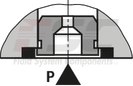
Throttle insert
The use of a throttle insert is required when due to prevailing operating conditions, flows can occur during the switching processes, which exceed the performance limit of the valve.
It is inserted in channel P of the directional valve.
Type 4WP 6 E6X/...
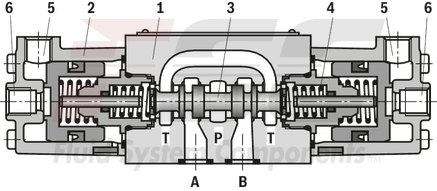
Without spring return, with detent,
version ..OF/..
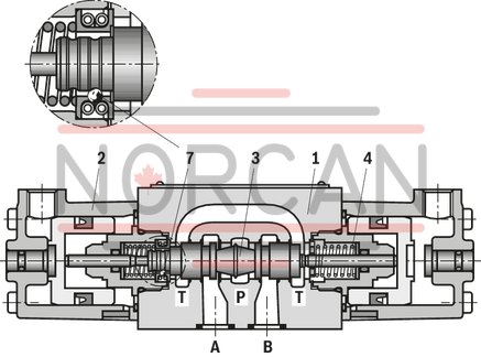
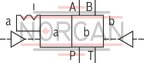
Directional valves with pneumatic actuation are also available as a 2-spool position valve with detent (7). If actuation elements with detent are used, each spool position can be locked.
Without spring return,
version ..O/..
If actuation elements without return springs and without detent are used, there is no defined spool position in the de-energized state.
Type 4WP 6 C6X/OF/N...
|
01 |
02 |
03 |
04 |
05 |
06 |
07 |
08 |
9 |
10 |
11 |
12 |
13 |
14 |
15 |
16 |
||
|
W |
P |
Z |
6 |
6X |
/ |
J |
/ |
* |
|
01 |
3 main ports |
3 |
|
4 main ports |
4 |
|
|
02 |
Directional valve |
W |
|
Type of actuation |
||
|
03 |
pneumatic |
P |
|
04 |
Ports, axial |
Z 1) |
|
05 |
Size 6 |
6 |
|
06 |
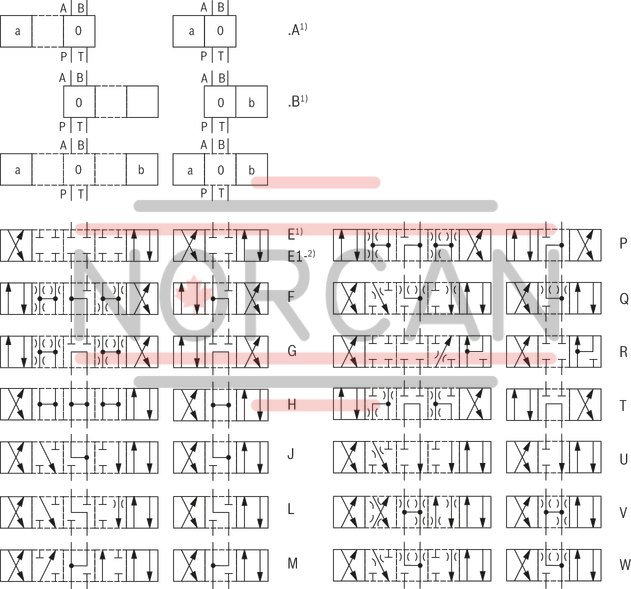
Spool symbol, e. g. C, E, EA, EB etc. 2) |
|
|
07 |
Component series 60 … 69 (60 … 69: unchanged installation and connection dimensions) |
6X |
|
08 |
With spring return |
no code |
|
Without spring return |
O |
|
|
Without spring return with detent |
OF |
|
|
09 |
Improved corrosion protection 3) |
J |
|
10 |
Without manual override |
no code |
|
With manual override |
N3) |
|
|
Spool position monitoring 7) |
||
|
11 |
Without position switch |
no code |
|
Monitored spool position "a" |
QMAG24 |
|
|
Monitored spool position "b" |
QMBG24 |
|
|
Monitored rest position |
QM0G24 |
|
|
12 |
Without throttle insert |
no code |
|
Throttle Ø 0.8 mm |
B086) |
|
|
Throttle Ø 1.0 mm |
B106) |
|
|
Throttle Ø 1.2 mm |
B126) |
|
|
Seal material |
||
|
13 |
NBR seals |
no code |
|
FKM seals |
V |
|
|
Observe compatibility of seals with hydraulic fluid used. (Other seals upon request) |
||
|
Clamping length |
||
|
14 |
42 mm (standard) |
no code |
|
22 mm |
Z |
|
|
15 |
Without locating hole |
no code |
|
With locating hole |
/605) |
|
|
With locating hole and locking pin ISO 8752-3x8-St |
/62 |
|
|
16 |
Further details in the plain text |
* |
Preferred types and standard units are specified in the EPS (standard price list).
|
Switching positions |
|||
|
2 |
3 |
Type WPZ |
|
|
no code |
● |
● |
● |
|
O |
● |
● |
|
|
OF |
● |
● |
|
|
● = available |
|||
| 1) Not with version “N” | |
| 2) For symbols and example, see Symbols and Types of actuation | |
| 3) The external parts made of metal are galvanized, treated with an anti-corrosion agent or made of stainless steel. This design is also suitable for on-wall applications. | |
| 5) Locking pin ISO 8752-3 x 8-St, material no. R900005694, separate order | |
| 6) Use if volume flow > performance limits of the valve, effective in channel P. | |
| 7) Not for version “J” |
general
|
Size |
6 | ||
|
Weight (approx.) |
Valve with one actuation cylinder |
kg |
1.8 |
|
Valve with two actuation cylinders |
kg |
2 | |
|
Installation position 1) |
any | ||
|
Ambient temperature range |
NBR seals |
°C |
-30 … +80 |
|
FKM seals |
°C |
-20 … +80 | |
| 1) | With version ../O.. (A, C and D) : horizontal |
hydraulic
|
Size |
6 | ||
|
Maximum operating pressure |
Port P |
bar |
315 |
|
Port A |
bar |
315 | |
|
Port B |
bar |
315 | |
|
Port T 1) |
bar |
160 | |
|
Maximum flow |
l/min |
60 | |
|
Flow cross-section (spool position 0) |
Symbol Q |
mm2 |
approx. 6 % of nominal cross-section |
|
Symbol W |
mm2 |
approx. 3 % of nominal cross-section | |
|
Minimum pilot pressure 2) |
bar |
4 | |
|
Maximum pilot pressure |
bar |
10 | |
|
Pilot volume |
cm³ |
4.24 | |
|
Hydraulic fluid |
see table | ||
|
Hydraulic fluid temperature range |
NBR seals |
°C |
-30 … +80 |
|
FKM seals |
°C |
-20 … +80 | |
|
Viscosity range |
mm²/s |
2.8 … 500 | |
|
Maximum admissible degree of contamination of the hydraulic fluid 3) |
Class 20/18/15 according to ISO 4406 (c) | ||
|
Maximum switching frequency |
Hz |
2 | |
| 1) | With symbols A and B, port T must be used as leakage oil connection if the operating pressure exceeds the admissible tank pressure. |
| 2) | See characteristic curves |
| 3) | The cleanliness classes specified for the components must be adhered to in hydraulic systems. Effective filtration prevents faults and simultaneously increases the life cycle of the components. For the selection of the filters, see www.boschrexroth.com/filter. |
|
Hydraulic fluid |
Classification |
Suitable sealing materials |
Standards |
|
|
Mineral oil |
HL, HLP |
FKM, NBR |
DIN 51524 |
|
|
Bio-degradable |
Insoluble in water |
HEES (synthetic esters) |
FKM |
VDMA 24568 |
|
HETG (rape seed oil) |
FKM, NBR |
|||
|
Soluble in water |
HEPG (polyglycols) |
FKM |
VDMA 24568 |
|
|
Other hydraulic fluids on request |
||||
Inductive position switch type QM: electrical connection
The electric connection is realized via a 4-pole mating connector (separate order) with connection thread M12 x 1.
electrical
|
Connection voltage (DC voltage) |
V |
24 | ||
|
Voltage tolerance (connection voltage) |
+30 %/-15 % | |||
|
Admissible residual ripple |
% |
≤ 10 | ||
|
Max. load capacity |
mA |
400 | ||
|
Switching outputs 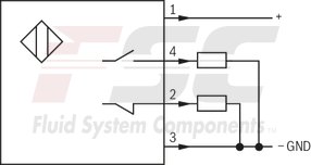
|
PNP transistor outputs, load between switching outputs and GND | |||
|
Pinout 
|
1 |
V |
24 | |
|
2, 4 |
Switching output |
mA |
400 | |
|
3 |
Earthing (GND) |
V |
0 | |
For applications outside these parameters, please consult us!
(measured with HLP46, ϑOil = 40 ±5 °C)
Δp-qV characteristic curves
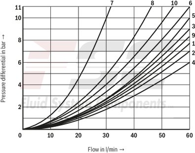
|
Symbol |
Direction of flow |
|||
|
P-A |
P-B |
A-T |
B-T |
|
|
A |
3 |
3 |
– |
– |
|
B |
3 |
3 |
– |
– |
|
C |
1 |
1 |
3 |
1 |
|
D |
5 |
5 |
3 |
3 |
|
E |
3 |
3 |
1 |
1 |
|
F |
1 |
3 |
1 |
1 |
|
G |
6 |
6 |
9 |
9 |
|
H |
2 |
4 |
2 |
2 |
|
J |
1 |
1 |
2 |
1 |
|
L |
3 |
3 |
4 |
9 |
|
M |
2 |
4 |
3 |
3 |
|
P |
3 |
1 |
1 |
1 |
|
Q |
1 |
1 |
2 |
1 |
|
R |
5 |
5 |
4 |
– |
|
T |
10 |
10 |
9 |
9 |
|
U |
3 |
3 |
9 |
4 |
|
V |
1 |
2 |
1 |
1 |
|
W |
1 |
1 |
2 |
2 |
|
Y |
5 |
5 |
3 |
3 |
|
Further characteristic curves: |
|
|
7 |
Symbol “R” in switching position “b” (B → A) |
|
8 |
Symbol “G” and “T” in central position (P → T) |
|
9 |
Symbol “H” in central position (P → T) |
Minimum pilot pressure dependent on the tank pressure
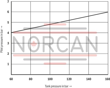
At a higher tank pressure, the minimum pilot pressure has to be increased according to this diagram.
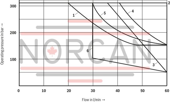
|
Characteristic curve |
Symbol |
|
1 |
A, B |
|
2 |
A/O, C, C/O, D, D/O, E, E1-, G, H, J, L, M, Q, U, W, und Y |
|
3 |
F, P |
|
4 |
R |
|
5 |
T |
|
6 |
V |
Attention!
Caution in conjunction with differential cylinders due to pressure intensification!
| 1) |
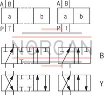
Example: – Symbol E with spool position "a" → ordering code ..EA.. – Symbol E with spool position “b” → ordering code ..EB.. |
| 2) | Symbol E1-: P → A/B pre-opening |
|
Ordering code |
Type of actuation |
||
|
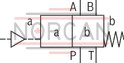
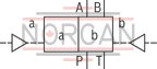
Symbol |
Actuation side |
Spool return |
|
|
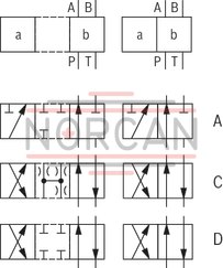
A, C, D |
|
||
|
../O.. |
|
||
|
../OF.. |
|
||
|
B, Y |
|
||
|
E, F G, H J, L M, P Q, R T, U V, W |
a = A |
|
|
|
b = B |
|
||
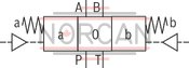
|
|||
Dimensions in mm
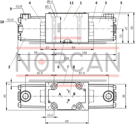
|
|
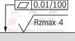
Required surface quality of the valve contact surface |
|
1 |
Valve with 2 spool positions and 2 actuation cylinders |
|
Valve with 3 spool positions and 2 actuation cylinders |
|
|
2 |
Actuation cylinder “a” |
|
3 |
Actuation cylinder “b” |
|
4 |
Plug screw for valve with 1 actuation cylinder (2 spool positions) |
|
6 |
Same seal rings for ports A, B, P, T |
|
7 |
Name plate |
|
8 |
Porting pattern according toISO 4401-03-02-0-05 (with locating hole for locking pin ISO 8752-3x8-St, material no. R900005694, separate order) |
|
9 |
Connection with version “WP” |
|
10 |
Port with version “WPZ” |
|
11 |
Alternative clamping length (): 22 mm |
Subplates according to data sheet 45052 (separate order)
(without locating hole)
G 341/01 (G1/4)
G 342/01 (G3/8)
G 502/01 (G1/2)
(with locating hole)
G 341/60 (G1/4)
G 342/60 (G3/8)
G 502/60 (G1/2)
G 341/12 (SAE-6)1)
G 342/12 (SAE-8)1)
G 502/12 (SAE-10)1)
1) On request
Valve mounting screws (separate order)
Clamping length 42 mm:4 hexagon socket head cap screws, metric
ISO 4762-M5 x 50-10.9-flZn-240h-L
(friction coefficient μtotal = 0.09 to 0.14);
tightening torque MA = 7 Nm ± 10 %,
material no. R913000064
or
4 hexagon socket head cap screws
ISO 4762-M5 x 50-10.9 (self procurement)
(friction coefficient μtotal = 0.12 to 0.17);
tightening torque MA = 8.1 Nm ± 10 %
4 hexagon socket head cap screws UNC
10-24 UNC x 2″ ASTM-A574
(friction coefficient μtotal = 0.19 to 0.24);
tightening torque MA = 11 Nm± 15 %,
(friction coefficient μtotal = 0.12 to 0.17);
tightening torque MA = 8 Nm ± 10 %,
material no. R978800693
Clamping length 22 mm:4 hexagon socket head cap screws, metric
ISO 4762-M5 x 30-10.9-flZn-240h-L
(friction coefficient μtotal= 0.09 to 0.14);
tightening torque MA = 7 Nm ± 10 %,
material no. R913000316
or
4 hexagon socket head cap screws
ISO 4762-M5 x 30-10.9 (self procurement)
(friction coefficient μtotal = 0.12 to 0.17);
tightening torque MA = 8.1 Nm± 10 %
4 hexagon socket head cap screws UNC
10-24 UNC x 1 1/4 ″
(friction coefficient μtotal = 0.19 to 0.24);
tightening torque MA = 11 Nm± 15 %,
(friction coefficient μtotal = 0.12 to 0.17);
tightening torque MA = 8 Nm± 10 %,
material no. R978802879
Spool position monitoring
Inductive position switch type QM
Dimensions in mm
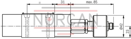
| 1) | For dimensions, see valve dimensions |
Notice:
The dimensions are nominal dimensions which are subject to tolerances.