
BOSCH REXROTH
R901151279
$517.15 USD
- BOSCH REXROTH
- Material:R901151279
- Model:KSDER1CB/HN11V
Quantity in stock: 0
The Bosch Rexroth KSDER1CB/HN11V (R901151279) is a high-performance directional poppet valve characterized by its direct operation with solenoid actuation. This screw-in cartridge valve is designed to manage flow with precision, featuring a maximum operating pressure of up to 350 bar (5076 psi) and a maximum flow rate of 80 l/min (21.1 gpm). It is engineered for use within the Sun TA cavity and employs an FKM sealing material for optimal performance in various hydraulic systems. The KSDER1CB/HN11V valve offers both normally open and normally closed configurations, ensuring versatility for different circuit designs. Its pressure-compensated structure allows consistent operation regardless of fluctuating pressures, while the solenoid-actuated on/off functionality provides reliable control for hydraulic circuits. The manual override feature, available in concealed or screwable versions, adds an extra layer of control by allowing manual operation in the absence of solenoid power. This model boasts a poppet-type spool ensuring tight sealing and minimal leakage across ports in its default position. Additionally, it has been designed to ensure reliable switching even after extended periods without activity, thanks to its wet-pin DC solenoids and the ability to rotate the solenoid coil for ease of installation. The Bosch Rexroth KSDER1CB/HN11V valve is compatible with a range of hydraulic fluids including HL, HLP, HETG, HEPG, and HEES types. Its robust construction and advanced design make it suitable for demanding applications where precise flow control and durability are critical. The product's direct acting feature offers simplicity and reliability in function, making it an essential component for efficient hydraulic system operations.
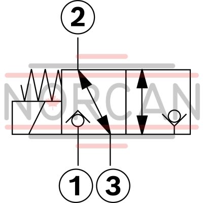
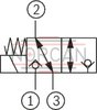
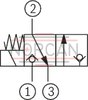
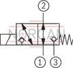
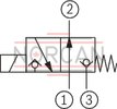
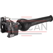
3/2 directional poppet valve, direct operated with solenoid actuation
Unpacked Weight: 0.3189 kg
General
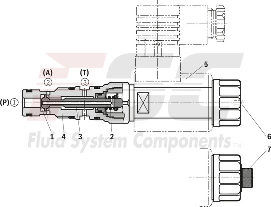
The 3/2 directional seat valves are direct operated, pressure-compensated screw-in cartridge valves. They basically consist of a screw-in section (4) with valve seat (1), solenoid (5) as well as closing element (3) and compression spring (2).
Function
The initial position of the valve (normally open “U" or normally closed “C") is determined by the position of the closing element (3) and the arrangement of the compression spring (2). Due to the structural design, the 3/2 directional seat valves are always pressure-compensated in relation to the actuating forces. The main ports ➀ and ➁ can be loaded with an operating pressure of 350 bar/500 bar (see Technical data) and are blocked in a leakage-free manner in the respective end position. While switching, the main ports are connected for a short period of time (negative overlap).
Attention!
The flow is only admissible in the direction of arrow (see symbols)! With version “U” (operating pressure 500 bar [7250 psi]) as well as with version “R...-17”, the main port ➀ is to be connected to the pump connection P! The valves of version “R...-17” are flow-optimized and thus achieve a greater switching power.
The manual override allows the switching of the valve without solenoid energization. It is available in concealed version "N9" (6) or in screwable version "N11" (7) (see ordering codes).
Version "K4" (with mating connector)
Type KSDER1UB/HN9V
Version "C4"
Version "K40"
| Screw-in cartridge valve |
| Maximum operating pressure 350 bar (5000 psi) |
| Maximum flow 12 l/min (3 gpm) |
| Cavity Sun T-11A |
| Max. pressure | 350 |
| Coil | GZ37 |
| Product family classification | 3/2 directional poppet valve, direct operated with solenoid actuation |
| Productgroup ID | 9,10,11,12,13,14 |
| Product family type | KSDE |
| Ports number | 3 |
| Manual override | Screw type manual override |
| Type of actuation | Solenoid-actuated on/off |
| Sealing material | FKM |
| Cavity | Sun T-11A |
| Product type | KSDE |
| Max. flow | 20 |
| Type of connection | Screw-in cartridge valve |
| Nominal flow | 20 |
| Direct - Pilot | Direct acting |
| Positions | 2 |
| Product family | 3 ways |
| Coil integrated | To be ordered separately |
| Spool Poppet | Poppet type |
| Weight | 0.3189 |
| Hydraulic fluid | HL,HLP,HETG,HEPG,HEES |
(valve without coil) 1)
|
01 |
02 |
03 |
04 |
05 |
06 |
07 |
08 |
09 |
10 |
|
|
KSDE |
1 |
B |
/ |
H |
V |
* |
|
01 |
Directional seat valve, direct operated, electrically operated |
KSDE |
|||||
|
02 |
Maximum operating pressure 500 bar |
U |
|||||
|
Maximum operating pressure 350 bar |
R |
||||||
|
03 |
Component size |
1 |
|||||
|
04 |
3 main ports |
||||||
|
„R“ (350 bar) |
„U“ (500 bar) „R...–17“ (350 bar) |
||||||
|
Symbols |
|
|
C |
||||
|
|
U |
|||||
|
05 |
Component series |
B |
|||||
|
06 |
High Performance and mounting cavity R/T-11A (see mounting cavity) |
H |
|||||
|
07 |
Without manual override |
N0 |
|||||
|
With concealed manual override |
N9 |
||||||
|
with screwable manual override (actuation by means of knurled screw) |
N11 |
||||||
|
Version |
Symbol C |
Symbol U |
|||||
|
N0 |
N9 |
N11 |
N0 |
N9 |
N11 |
||
|
R (350 bar) |
X |
– |
X |
X |
X 2) |
– |
|
|
U (500 bar) |
X |
– |
– |
X |
– |
– |
|
|
Seal material |
|||||||
|
08 |
FKM seals (other seals upon request) |
V |
|||||
|
Observe compatibility of seals with hydraulic fluid used. |
|||||||
|
09 |
Standard |
no code |
|||||
|
Flow-optimized 3) |
–17 |
||||||
|
10 |
Further details in the plain text |
* |
|||||
| 1) Complete valves with mounted coil available on request | |
| 2) Screwable manual override “N10” (actuation by means of internal hexagon with lock nut), possible as separate order, material no. R901051231; ordering code “N9” ! | |
| 3) Version “R” only (free-flowing on one side!) |
general
|
Size |
1 | ||
|
Weight |
Valve |
kg |
0.3 |
|
Coil |
kg |
0.25 | |
|
Installation position |
any | ||
|
Ambient temperature range |
°C |
-40 … +110 | |
hydraulic
|
Size |
1 | |||
|
Maximum operating pressure |
Version |
„U“ | „R“ | |
|
bar |
500 1) | 350 2) | ||
|
Version “R...-17” 1) |
bar |
350 | ||
|
Maximum flow |
Version |
„U“ | „R“ | |
|
l/min 3) |
6 | 12 | ||
|
Version “R...-17” |
l/min |
20 3) | ||
|
Hydraulic fluid |
see table | |||
|
Hydraulic fluid temperature range |
°C |
-40 … +80 | ||
|
Viscosity range |
mm²/s |
4 … 500 | ||
|
Maximum admissible degree of contamination of the hydraulic fluid 4) |
Class 20/18/15 according to ISO 4406 (c) | |||
|
Load cycles |
Version (R: 350 bar [5100 psi]; U: 500 bar [5100 psi]) |
„U“ | „R“ | |
|
million |
5 | 10 | ||
|
Maximum tank pressure 5) |
bar |
≤ 50 | ||
| 1) | At main port ➀ and ➁ if P ≥ A ≥ T; for design reasons |
| 2) | At main port ➀ and ➁ |
| 3) | See performance limits |
| 4) | The cleanliness classes specified for the components must be adhered to in hydraulic systems. Effective filtration prevents faults and simultaneously increases the life cycle of the components. For the selection of the filters, see www.boschrexroth.com/filter. |
| 5) | At main port ➂ |
|
Hydraulic fluid |
Classification |
Suitable sealing materials |
Standards |
|
|
Mineral oil |
HL, HLP |
FKM, NBR |
DIN 51524 |
|
|
Bio-degradable |
Insoluble in water |
HEES (synthetic esters) |
FKM |
VDMA 24568 |
|
HETG (rape seed oil) |
FKM, NBR |
|||
|
Soluble in water |
HEPG (polyglycols) |
FKM |
VDMA 24568 |
|
|
Other hydraulic fluids on request |
||||
With the electrical connection "K4", the protective earthing conductor (PE, grounded) is to be connected in accordance with the stipulations.
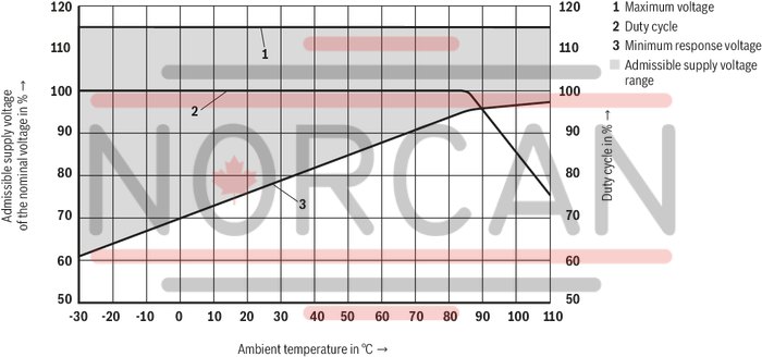
electrical
|
Voltage type |
Direct voltage | |||
|
Power supply 1) |
V |
12 24 |
||
|
Voltage tolerance against ambient temperature |
See characteristic curves | |||
|
Power consumption |
W |
22 | ||
|
Duty cycle |
% |
100 | ||
|
Maximum coil temperature 2) |
°C |
150 | ||
|
Switching time according to ISO 6403 (solenoid horizontal) 3) |
ON (➀ → ➁) |
ms |
≤ 60 | |
|
OFF (➁ → ➀) |
ms |
≤ 60 | ||
|
Maximum switching frequency |
Version |
„U“ | „R“ | |
|
Hz |
3600 | 9000 | ||
|
Protection class according to DIN EN 60529 |
Version "K4" |
IP65 (with mating connector mounted and locked) | ||
|
Version "C4" |
IP66 with mating connector mounted and locked IP69K with Rexroth mating connector (material no. R901022127) |
|||
|
Version "K40" |
IP69K with mating connector mounted and locked | |||
| 1) | Other voltages upon request |
| 2) | Due to the surface temperatures of the solenoid coils, the standards ISO 13732-1 and EN 982 need to be adhered to! |
| 3) | ≤ 95 with version “R...-17” |
For applications outside these parameters, please consult us!
Voltage tolerance against ambient temperature; duty cycle
Voltage range and duty cycle dependent on the ambient temperature
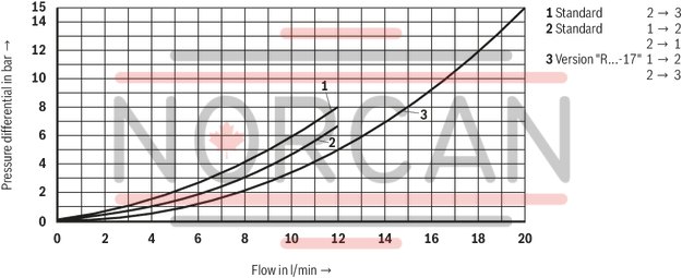
Δp-qV characteristic curves
(measured with HLP46, ϑOil = 40 °C ± 5 °C) and 24 V coil
Performance limits (measured with HLP46, ϑOil = 40 ±5 °C and 24 V coil)
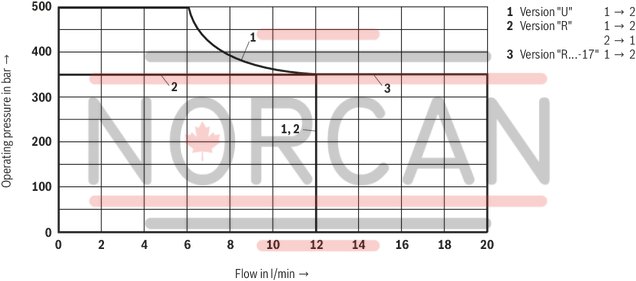
Attention!
The performance limit has been determined with the solenoids at operating temperature and with 10% undervoltage.
(measured with HLP46, ϑoil = 40 ±5 °C) and 24 V coil
Version “R”(350 bar)
Symbol “C“ normally closed
Symbol “U“ normally open
Version “U” (500 bar) and “R…-17” (350 bar)
Symbol “C“ normally closed
Symbol “U“ normally open
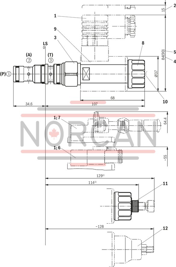
Dimensions in mm
|
1 |
Mating connector (separate order) |
|
2 |
Space required to remove the mating connector |
|
3 |
SW24, tightening torque MA = 60+5 Nm |
|
4 |
Dimension for mating connector “K4”, without circuitry |
|
5 |
Dimension () for mating connector “K4”, with circuitry |
|
6 |
Version "K40" |
|
7 |
Version "C4" |
|
8 |
Nut, tightening torque MA = 5+1 Nm |
|
9 |
Coil (separate order) |
|
10 |
Concealed manual override "N9", optional |
|
11 |
Screwable manual override "N11", optional |
|
12 |
Screwable manual override “N10” (separate order) |
|
➀ |
Main port 1, pump P3) |
|
➁ |
Main port 2, actuator A3) |
|
➂ |
Main port 3, tank T3) |
|
LS |
Location shoulder |
| 1) actuated | |
| 2) screwed in | |
| 3)Attention! | |
| Unambiguous pin assignment. P, A and T must not be exchanged or closed! |
Mounting cavity R/T-11A; 3 main ports; thread M20 x 1.5 mm
Dimensions in mm
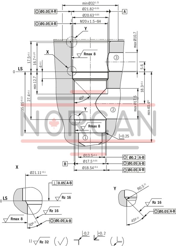
| 1) Deviating from T-11A | |
| 2) All seal ring in sertion faces are rounded and free of burrs | |
| 3) With countersink | |
| 4) Depth for mobile parts |
|
➀ |
Main port 1 |
|
➁ |
Main port 2 |
|
➂ |
Main port 3 |
|
LS |
Location shoulder |
|
Tolerance for all angles ± 0.5 ° |
|
Mating connectors for directional valves with connector "C4" and "C4Z" (AMP Junior-Timer), litz wire outer diameter 2.2 mm to 3.0 mm
2P JUNIOR D2 2
Mating connectors for directional valves with connector "C4" and "C4Z" (AMP Junior-Timer), litz wire outer diameter 2.2 mm to 3.0 mm
2P JUNIOR D2 2
For directional valves with connector "C4" and "C4Z" (AMP Junior-Timer)Data sheet
Spare parts & repair