

BOSCH REXROTH
R901152637
- BOSCH REXROTH
- Material:R901152637
- Model:VT-VSPA1-11-1X/V0/0
Due to extremely high demand, please call 877-366-7226 for availability
The Bosch Rexroth VT-VSPA1-11-1X/V0/0 (R901152637) is an advanced amplifier card designed for precise control of proportional valves. This component, belonging to series X in the Eurocard format, is specifically engineered for valves such as ZDRE...X, DREM...X, and ZDBE...X. It features a power output stage that supplies a clocked solenoid current to the proportional valve and is safeguarded against short circuits and internal faults by deenergizing when necessary. The unit includes an actual value output that provides feedback on solenoid current and voltage values. Its sophisticated fault recognition system monitors the solenoid conductor for cable breaks and short circuits, ensuring operational safety by providing voltage outputs and LED indicators corresponding to the system's status. The VT-VSPA1-11-1X/V0/0 also comes equipped with a characteristic curve generator that adjusts the command value signal to achieve a linear command value pressure characteristic curve. This can be configured using onboard jumpers. Additionally, it incorporates an amplitude limiter to prevent overloading by capping the internal command value. For dynamic control, it utilizes a clock generator that sets the frequency for the output stage which can be adjusted via a frequency potentiometer or jumpers for universal applications. The device offers external ramp time settings through an external potentiometer or voltage presetting, allowing users to extend ramp times beyond internal defaults. Moreover, this model includes an enable function that activates the power output stage and controls valve opening speed to prevent abrupt movements. The ramp generator further refines this process by limiting the slope of control output. Lastly, Bosch Rexroth's VT-VSPA1-11-1X/V0/0 is equipped with a robust power supply unit with making current limiter and supports various command value presetting options including differential inputs for voltage/current signals. It also features reverse polarity protection for operating voltage as well as short-circuit protection and cable break detection of the solenoid conductor ensuring reliable operation in various industrial applications.
Via the "frequency" potentiometer, the frequency can be corrected by > ±10 % (J6 and J7 closed).
Power output stage [14]
The power output stage creates a clocked solenoid current for the proportional valve.
The output stage output is de-energized in case of an internal fault signal or if the enable is missing. The output stage output is short-circuit-proof.
Actual value output [15]
1 mA (Isolenoid) ≙ 1 mV (actual value output)
Fault recognition [16]
The solenoid conductor is monitored for cable break and short-circuits. If there is no fault, a voltage >16 V is output at the “ready for operation” output and the “ready for operation” LED is illuminated.
In case of a fault, the following applies:
Characteristic curve generator [10]
Using the potentiometer "Gw" [11], the maximum current for the solenoid is set. In the characteristic curve generator [10], the command value signal is changed so that a linear command value pressure characteristic curve is created. For this purpose, the characteristic curve generator [10] has to be activated using jumper J4 and jumper J5 has to be opened.
In order to deactivate the characteristic curve, jumper J4 has to be opened and jumper J5 has to be closed.
Amplitude limiter [11]
The internal command value is limited to approx. +120 % of the nominal range
Command value output [12]
0 % ≙ 0 V
+100 % ≙ +10 V
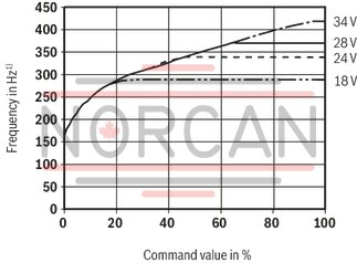
Clock generator [13]
In the clock generator [13], a frequency for the output stage is generated. The frequency is influenced by the supply voltage.
Via the jumper J6, a frequency depending on the command value signal is generated. For a universal use, jumper J6 is to be opened.
A frequency adjustment via the "frequency" potentiometer can be realized by means of jumper J7.
Example 1:
(Frequency adjustment via “frequency” potentiometer – without command value dependency; J6 = open, J7 = closed)
Setting range for VT-VSPA1-10: 180 Hz ... 400 Hz ±15 %
Setting range for VT-VSPA1-11: 210 Hz ... 310 Hz ±15 %
Example 2:
(command value-dependent frequency – J6 = closed)
External ramp time setting [9]
Using an external potentiometer or external voltage presetting (according to the formula in the "Ramp generator” section), the internally set ramp time can be extended. The setting can be verified by means of the measuring sockets. In case of a cable break, the internal default setting will be valid automatically.
The following applies to the external potentiometer:
Formula to calculate the ramp times:
; t in ms, U in Volt at the measuring socket
Ramp on/off [8]
Using jumper J2 or the “ramp on/off” input [8] (see terminal assignment), the ramp time is set to a minimum (<50 ms).
An activated ramp is displayed by an LED.
There is no switch-over between current and voltage input. The inputs are permanently available [see block diagram].
Enable function [6]
The enable function [6] enables the power output stage and forwards the internal command value signal to the ramp generator [7]. The enable signal is displayed by an LED. If the enable is connected (via 24 V input or jumper J1), the internal command value is changed [with any kind of command value presetting] by the set ramp time. Thus, a controlled valve does not open abruptly.
Ramp generator [7]
The ramp generator [7] limits the incline of the control output. The downstream amplitude limiter [11] does not extend or shorten the ramp time. Using the jumper J3, the ramp time is changed by the factor 10.
The following applies:
Power supply unit [1]
The amplifier is equipped with a power supply unit with making current limiter. This unit supplies all internally required positive and negative supply voltages.
Command value presetting [2], [3], [4], [5]
The internal command value signal is calculated from the total [5] of the external command value signal available at the differential input [2] or at the current input [3] and the zero point offset [4] (zero point potentiometer "Zw").
The following applies:
| 1) | 1) Tolerance ±15 % |
|
Outlet |
LED |
|
|
Short-circuit |
low |
off |
|
Cable break |
clocked |
flashing |
|
Setting range |
||
|
min. ramp time (potentiometer at left turn) |
max. ramp time (rotary angle of the potentiometer at approx. 95%) |
|
|
1 kΩ |
100 ms |
1 s |
|
100 Ω |
1 s |
10 s |
|
The minimum ramp time can only be reached if the internally set ramp time is lower, i.e. the corresponding potentiometer is at the left turn. The specified ramp times are true for J3 = open. |
||
|
“Ramp on/off” input |
LED "T" |
Ramp |
|
|
0 V |
open |
on |
on |
|
24 V |
open |
off |
off |
|
0 V |
closed |
off |
off |
|
24 V |
closed |
on |
on |
|
Usocket/V |
1 |
0.2 |
0.1 |
0.02 |
|
|
open (default setting) |
t/ms |
100 |
500 |
1000 |
5000 |
|
closed |
t/s |
1 |
5 |
10 |
50 |
|
Standard values |
Current input |
Differential input |
Command value socket |
|
0 % |
4 mA |
0 V |
0 V |
|
+100 % |
20 mA |
+10 V |
+10 V |
|
01 |
Valve amplifier for proportional pressure valves, analog, euro-card format |
VT-VSPA1 |
|
02 |
For valves: |
11 |
|
03 |
Component series 10 ... 19 (10 ... 19: unchanged installation and connection dimensions) |
1X |
|
04 |
Version: standard |
V0 |
|
05 |
Option: standard |
0 |
|
06 |
Further details in the plain text |
* |
|
01 |
02 |
03 |
04 |
05 |
06 |
||||
|
VT-VSPA1 |
‒ |
11 |
‒ |
1X |
/ |
V0 |
/ |
0 |
*
|
General
|
Type of electronics |
Analog | ||
|
Design |
Euro-card |
Voltage supply
|
Operating voltage |
nominal |
U |
V |
24 |
|
Lower limit value |
UB(t)min |
V |
18 | |
|
Upper limit value |
UB(t)max |
V |
35 | |
|
Power consumption |
max. |
Smax |
VA |
24 |
|
Current consumption |
max. |
Imax |
A |
2 |
|
Fuse |
2 A medium time-lag, exchangeable | |||
Analog inputs
|
Command value |
Voltage (differential input) |
U |
V |
0 ... 10 | |
|
Voltage (differential input) |
Input resistance |
R |
kΩ |
≥ 50 | |
|
Current |
I |
mA |
4 … 20 | ||
|
Current |
Input resistance |
R |
Ω |
100 | |
Digital inputs
|
Enable |
On (active) 1) |
U |
V |
8.5 ... UB |
|
Off (inactive) |
U |
V |
0 ... 6.5 | |
|
Ramp on/off |
On (active) 1) |
U |
V |
8.5 ... UB |
|
Off (inactive) |
U |
V |
0 ... 6.5 |
| 1) | RE > 100 kΩ |
Analog outputs
|
Internal command value |
U |
V |
0 ... 10 ±2% (Imax = 2 mA) | |
|
Actual current value |
U |
V |
0 ... 1.9 ±2% (mV ≙ mA), Imax = 2 mA | |
Digital outputs
|
Ready for operation 1) |
On (active) |
U |
V |
16 ... UB |
|
Ready for operation |
Off (inactive) |
U |
V |
0 ... 1 |
| 1) | Imax = 50 mA |
Solenoid outputs
|
Clock frequency |
Factory setting |
f |
Hz |
250 ±10 % |
|
Clock frequency 1) |
Setting range |
f |
Hz |
210 ... 310 |
|
Solenoid output |
other properties |
Short-circuit-proof, clocked |
| 1) | Tolerance ±15%, for universal use |
Adjustment options
|
Zero point calibration |
% |
± 30 | ||
|
Amplitude attenuator |
for command value |
% |
0 ... 120 | |
|
Ramp time up/down |
Ramp 1 |
t |
s |
0.02 … 5 |
|
Ramp 2 |
t |
s |
0.2 … 50 | |
Measuring sockets
|
Command value |
"w" |
Uw |
V |
0 ... 10 |
|
Actual value |
I |
i |
A |
0 ... 1.9 (mV ≙ mA) |
|
Rampenzeit |
“down" |
Udown |
V |
0.01 ... 5 |
|
“up" |
Uup |
V |
0.01 ... 5 | |
|
additional notices |
See Function |
Displays
|
LED display |
Green 1 |
Ready for operation | |
|
Yellow 1 |
Enable | ||
|
Yellow 2 |
Ramp on |
Other information
|
Reference voltage |
Potentiometer supply |
U |
V |
10 ±2% (Imax = 25 mA, short-circuit-proof) |
|
Anschlussart |
48-pole male multipoint connector, DIN 41612, design F | |||
|
Ambient temperature range |
ϑ |
°C |
0 … 50 | |
|
Storage temperature range |
ϑ |
°C |
-25 … 85 | |
|
Weight |
m |
kg |
0.15 | |
For applications outside these parameters, please consult us!
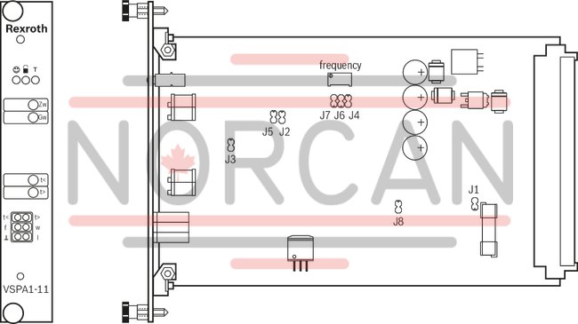
Potentiometer
|
Zw |
Zero point |
|
Gw |
Amplitude attenuator |
|
t < |
Ramp time "Ramp up" |
|
t > |
Ramp time "Ramp down" |
|
frequency |
Clock frequency of the output stage |
Measuring sockets
|
t < |
Ramp time "Ramp up" |
|
t > |
Ramp time "Ramp down" |
|
w |
Command value |
|
I |
Actual current value (mV ≙ mA) |
|
f |
Clock frequency of the output stage |
|
⊥ |
Reference potential |
LED displays
|
|
Ready for operation (green) |
|
|
Enable (yellow) |
|
T |
Ramp on |
|
Jumper |
Function |
Factory setting |
|
|
open |
No enable |
● |
|
|
closed |
Enable activated |
||
|
open |
Ramp function on/off (see table under Function) |
● |
|
|
closed |
|||
|
open |
Ramp time 0.02 ... 5 s |
● |
|
|
closed |
Ramp time 0.2 ... 50 s |
||
|
open |
Command value pressure characteristic curve correction inactive |
||
|
closed |
Command value pressure characteristic curve correction active |
● |
|
|
open |
Command value pressure characteristic curve correction active |
● |
|
|
closed |
Command value pressure characteristic curve correction inactive |
||
|
open |
Command value-dependent frequency deactivated |
||
|
closed |
Command value-dependent frequency activated (ZDRE 10, 3DRE(M) 10 and 16) |
● |
|
|
open |
Frequency adjustment via "frequency" potentiometer deactivated |
● |
|
|
closed |
Frequency adjustment via "frequency" potentiometer activated |
||
|
closed |
Reserve jumper |
● |
|
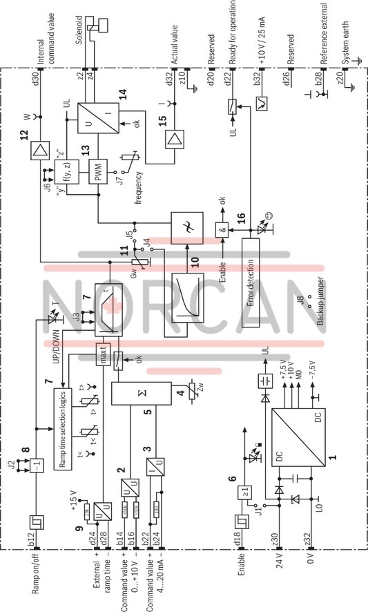
|
1 |
Power supply unit |
|
2 |
Differential input |
|
3 |
Current input |
|
4 |
Zero point setting |
|
5 |
Command value summation |
|
6 |
Enable |
|
7 |
Ramp generator |
|
8 |
Ramp on/off |
|
9 |
External ramp time |
|
10 |
Characteristic curve generator |
|
11 |
Amplitude limiter |
|
12 |
Command value output |
|
13 |
Clock generator |
|
14 |
Power output stage |
|
15 |
Actual value output |
|
16 |
Fault recognition |
|
J1...J8 |
See Operating and display elements |
Dimensions in mm

Dimensions in mm

The amplifier card may only be assembled when de-energized.
No connectors with free-wheeling diodes or LED displays must be used for the solenoid connection.
Only carry out measurements at the card using instruments Ri>100 kΩ.
For switching command values, relays with gold-plated contacts have to be used (low voltages, low currents).
Always shield command value lines, connect shielding to earth on the card-side, other side open. If no system earth exists, connect 0 V operating voltage.
Recommendation:
Also shield the solenoid conductors. For solenoid conductors up to 50 m in length, use the line type LiYCY 1.5 mm2. For greater lengths, please contact us.
The distance to aerial lines, radios, and radar systems has to be at least 1 m.
Do not lay solenoid conductors and signal lines near power lines.
If the differential input is used, both inputs must always be connected or disconnected simultaneously.