


BOSCH REXROTH
R901189134
- BOSCH REXROTH
- Material:R901189134
- Model:4WRPNH 6 C4 B40L-2X/M/24PA6B
Due to extremely high demand, please call 877-366-7226 for availability
The Bosch Rexroth 4WRPNH6C4B40L-2X/M/24PA6B (R901189134) is a state-of-the-art direct operated high-response valve equipped with an integrated digital axis controller (IACR). This advanced component combines the precision of flow, position, and pressure control with the versatility of pQ function, substitutional position-pressure, or position-force control, and NC functionality. It is designed for tasks requiring exacting hydraulic control with rapid response times. The valve is distinguished by its capability to accept command value presetting through either an analog interface or a field bus interface. Actual value signals can be provided via an analog interface and can also be read out through the field bus for real-time monitoring. The configuration and parameter setting are facilitated via the same field bus connection, ensuring ease of integration into existing systems. For diagnostics and parameterization, the WinHPT commissioning software is utilized. This software supports Windows 7 or Windows XP operating systems and offers features like programming of NC functionality, error diagnosis, and data management on a PC. The integrated control electronics within the valve enable detection of issues such as cable breaks, undervoltage conditions, temperature variations in electronics, communication errors, and watchdog timer lapses. Additional functions supported by this Bosch Rexroth valve include ramp generation, internal command value profiles, enable function toggle between analog/digital modes, error output signaling compatible with PLC logic systems up to 0.5 A output current capacity. It also provides actuating variable adaptation along with dead band compensation, zero point correction, valve inflection compensation as well as friction compensation which includes direction-dependent amplification. This high-response valve operates on one side with a failsafe position when switched off. Its interfaces support multiple sensor types including two analog sensors (0-10 V or 4...20 mA), one length measurement system (1 Vpp or SSI), plus additional analog sensors for comprehensive feedback options. Command values can be preset or responded to in analog current or voltage formats through a field bus connection that supports CAN bus with CANopen protocol DS-402 and Profibus-DP VoV protocols. The model has a size designation of 6X indicating its physical dimensions within Bosch Rexroth's product range. It can handle maximum operating pressures up to 315 bar and facilitate maximum flow rates up to 40 liters per minute. With these capabilities embedded in its design, this Bosch Rexroth valve stands as a versatile solution for sophisticated hydraulic control applications demanding high levels of accuracy and responsiveness.
Set-up:
The IAC-R valve basically consists of:
Direct operated high-response valve (1) with control spool and sleeve in servo quality Integrated digital axis controller (2) with analog and digital sensor interfaces and field bus connection (X3)High-response valve with integrated axis controller with analog interfaces (X1, X4, X7)
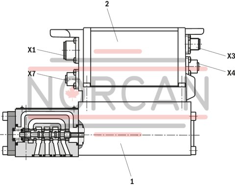
High-response valve with integrated axis controller with analog interfaces (X1, X4) and digital interface (X7)
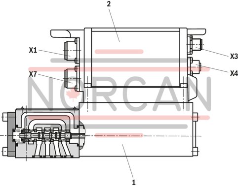
Functional description
The IAC-R valve (Integrated Axis Controller based on high-response valves) is a digital high-response valve with integrated axis controller and the following functionalities:
Flow control Position control Pressure control p/Q function Substitutional position/pressure or position/force control NC functionalityThe command value presetting can alternatively be specified via an analog interface (X1) or via the field bus interface (X3) The actual value signals are provided via an analog interface (X1) and can additionally be read out via the field bus (X3). The controller parameters are set via the field bus. Separate supply voltage for bus/controller and power part (output stage) for safety reasons
WinHPT PC program
To implement the project planning task and to parameterize the IAC-R valves, the user may use the WinHPT commissioning software (see accessories):
Parameterization Programming of NC functionality Diagnosis Comfortable data management on a PC PC operating systems: Windows 2000 or Windows XP
The digital integrated control electronics enables the following error detection:
Cable break sensor technology Undervoltage Temperature of the integrated electronics Communication error Watchdog
The following additional functions are available:
Ramp generator Internal command value profile Enable function, analog/digital Error output 24 V (e.g. as switching signal to PLC/logic and additional valves), max 1.8 A Actuating variable adaptation Dead band compensation Zero point correction Valve inflection compensation Friction compensation direction-dependent amplification
|
01 |
02 |
03 |
04 |
05 |
06 |
07 |
08 |
09 |
10 |
11 |
12 |
13 |
14 |
15 |
|||
|
4WRP |
N |
H |
B |
‒ |
2X |
/ |
M |
/ |
24 |
* |
|
01 |
High-response valve, direct operated |
4WRP |
|
02 |
With integrated digital axis controller and NC functionality |
N |
|
03 |
Control spool/sleeve |
H |
|
04 |
Size 6 |
6 |
|
Size 10 |
10 |
|
|
05 |
Symbols; for the possible version, see "Symbols/Circuit diagrams" |
C, C1, C3, C4, C5 |
|
06 |
Installation side of the inductive position transducer 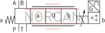
|
B |
|
Rated flow at 70 bar valve pressure differential (35 bar/control edge) |
||
|
07 |
Size 6 |
|
|
2 l/min |
02 |
|
|
4 l/min |
04 |
|
|
12 l/min |
12 1) |
|
|
15 l/min |
15 2) |
|
|
24 l/min |
24 1) |
|
|
25 l/min |
25 2) |
|
|
40 l/min |
40 3) |
|
|
Size 10 |
||
|
50 l/min |
50 |
|
|
100 l/min |
100 |
|
|
Flow characteristic |
||
|
08 |
Linear |
L |
|
Inflected characteristic curve (inflection 60 % for NG6 with rated flows "15" and "25", otherwise inflection 40 %) |
P 4) |
|
|
09 |
Component series 20 ... 29 (20 ... 29: unchanged installation and connection dimensions) - Size 6 |
2X |
|
Seal material |
||
|
10 |
NBR seals Suitable for mineral oils (HL, HLP) according to DIN 51524 |
M |
|
11 |
Supply voltage 24 V |
24 |
|
Fieldbus interface |
||
|
12 |
CANopen |
C 5) |
|
Profibus DP V0/V1 |
P |
|
|
Command value inputs |
||
|
13 |
±10 VDC |
A6 |
|
4 ... 20 mA |
F6 |
|
|
Sensor interfaces |
||
|
14 |
X4, M12-5, ±10V; X7, M12-5, ±10V |
A 6) |
|
X4, M12-5, ±10V; X7, M23-12, SSI 4) |
B 6, 7) |
|
|
X4, M12-5, ±10V; X7, M23-12, 1Vpp 5) |
C 6, 8) |
|
|
X4, M12-5, 4...20 mA; X7, M12-5, 4...20 mA |
G 6) |
|
|
X4, M12-5, 4...20 mA; X7, M23-12, SSI 4) |
H 6, 7) |
|
|
15 |
Further details in the plain text |
* |
|
1) |
Use only in connection with flow characteristics "L" |
|
|
2) |
Use only in connection with flow characteristics "P" |
|
|
3) |
qv 2:1 only with rated flow = 40 l/min |
|
|
4) |
Inflection 60 % for NG6 with rated flows "15" and "25", otherwise inflection 40 % |
|
|
5) |
Fieldbus interface CANopen with sensor interface "B", "C", "G" or "H" on request |
|
|
6) |
At sensor interfaces "A", "B" or "C", only command value input "A6" is available. At sensor interfaces "G" and "H", only command value input "F6" is available. |
|
|
7) |
Gray code or binary |
|
|
8) |
Adjustable interpolation |
|
For applications outside these parameters, please consult us!
general
|
Type |
4WRPNH.../24/C/P | ||
|
Size |
6 | 10 | |
|
Component series |
2X | ||
|
Design |
Directional spool valve, direct operated, with steel sleeve | ||
|
Type of actuation |
Proportional solenoid with position control, OBE | ||
|
Type of connection |
Plate connection, porting pattern according to ISO 4401 | ||
|
Installation position |
Any | ||
|
Weight |
kg |
2.7 | 7.5 |
|
Ambient temperature range |
°C |
-20 … +50 | |
hydraulic
|
Type |
4WRPNH.../24/C/P | |||
|
Size |
6 | 10 | ||
|
Maximum operating pressure |
bar |
315 | ||
|
Maximum operating pressure |
Port P |
bar |
315 | |
|
Port A |
bar |
315 | ||
|
Port B |
bar |
315 | ||
|
Port T |
bar |
250 | ||
|
Maximum flow |
l/min |
100 | ||
|
Hydraulic fluid temperature range |
°C |
-20 … +60 | ||
|
Viscosity range |
Maximum admissible |
mm²/s |
10 … 800 | |
|
Recommended |
mm²/s |
20 … 100 | ||
|
Maximum admissible degree of contamination of the hydraulic fluid, cleanliness class according to ISO 4406 (c) 1) |
Class 18/16/13 according to ISO 4406 (c) | |||
|
Hysteresis |
% |
≤ 0.2 | ||
|
Manufacturing tolerance |
% |
< 10 | ||
|
Actuating time |
Signal step 0 … 100% |
ms |
10 | 25 |
|
Temperature drift |
% |
< 1 | ||
| 1) | The cleanliness classes specified for the components must be adhered to in hydraulic systems. Effective filtration prevents faults and simultaneously increases the life cycle of the components. For the selection of the filters, see www.boschrexroth.com/filter. |
hydraulic
|
Nominal flow 1) |
l/min |
50 | 100 | 50 | 100 | 2 | 4 | 12 | 15 | 24, 25 | 40 | |
|
Limitation of use |
Symbols C, C3, C5 |
bar |
315 | 160 | 315 | 160 | 315 | 160 | ||||
|
Symbols C1, C4 |
bar |
250 | 100 | 250 | 100 | 315 | 280 | 250 | 100 | |||
|
Zero flow |
Linear characteristic curve “L” |
l/min |
< 1200 | < 1500 | < 1200 | < 1500 | < 150 | < 180 | < 300 | - | < 500 | < 900 |
|
Inflected characteristic curve "P" |
l/min |
< 600 | < 500 | < 600 | - | < 180 | < 300 | < 450 | ||||
| 1) | With Δp = 35 bar/control edge |
|
Hydraulic fluid |
Classification |
Suitable sealing materials |
Standards |
|
Mineral oils and related hydrocarbons |
HL, HLP, HLPD, HVLP, HVLPD |
NBR / FKM |
DIN 51524 |
|
Important information on hydraulic fluids: For more information and data on the use of other hydraulic fluids please contact us. The flash point of the process and operating medium used must be 40 K over the maximum solenoid surface temperature. There may be limitations regarding the technical valve data (temperature, pressure range, life cycle, maintenance intervals, etc.). |
|||
electrical
|
Type |
4WRPNH.../24/C/P | |||
|
Size |
6 | 10 | ||
|
Power supply |
Nominal voltage |
VDC |
24 | |
|
Lower limit value |
VDC |
21 | ||
|
Upper limit value |
VDC |
36 | ||
|
Duty cycle |
% |
100 | ||
|
Maximum power consumption |
W |
40 | 60 | |
|
Protection class according to DIN EN 60529 |
IP65 (with mating connector mounted and locked) | |||
|
AD/DA resolution |
Analog inputs |
bits |
12 | |
|
Analog outputs |
bits |
10 | ||
(measured with HLP46, ϑÖl = 40 ±5 °C)
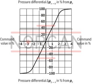
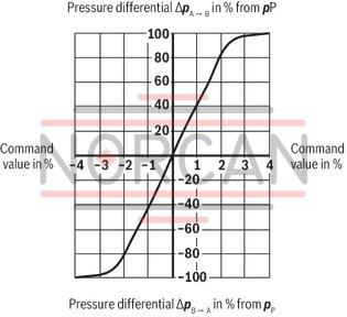
Pressure amplification
NG6
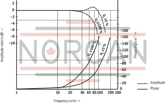
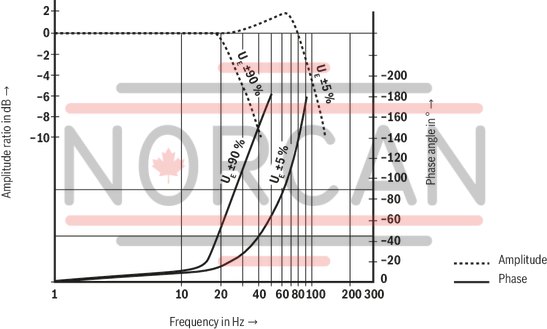
Frequency response
NG6
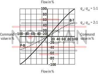
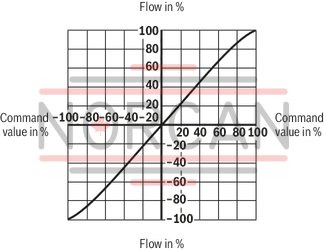
Linear characteristic curve “L”
NG6
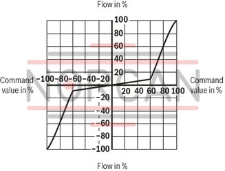
Inflected characteristic curve "P", inflection at 60 %
NG6
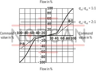
Inflected characteristic curve "P", inflection at 40 %
NG6
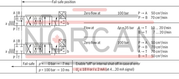
Fail-safe position
NG6
Pressure amplification
Size 10
Frequency response
Size 10
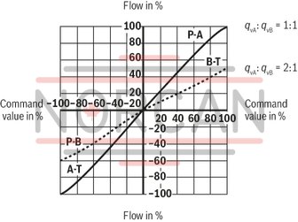
Linear characteristic curve "L" (1:1)
Size 10
Linear characteristic curve "L" (2:1)
Size 10
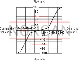
Inflected characteristic curve "P", inflection at 40 % (1:1)
Size 10
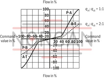
Inflected characteristic curve "P", inflection at 40 % (2:1)
Size 10
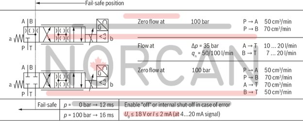
Fail-safe position
Size 10
Symbols
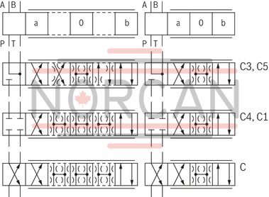
|
With control symbol C1 and C5, the following applies: |
|
|
P → A: qvmax |
B → T: qv/2 |
|
P → B: qv/2 |
A → T: qvmax |
NG6
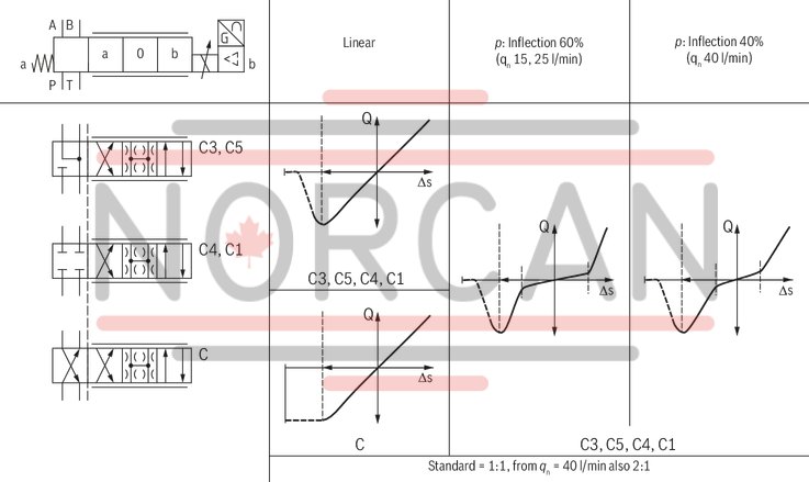
Size 10
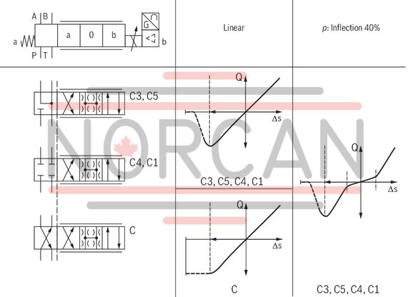
Block diagram / pin assignment
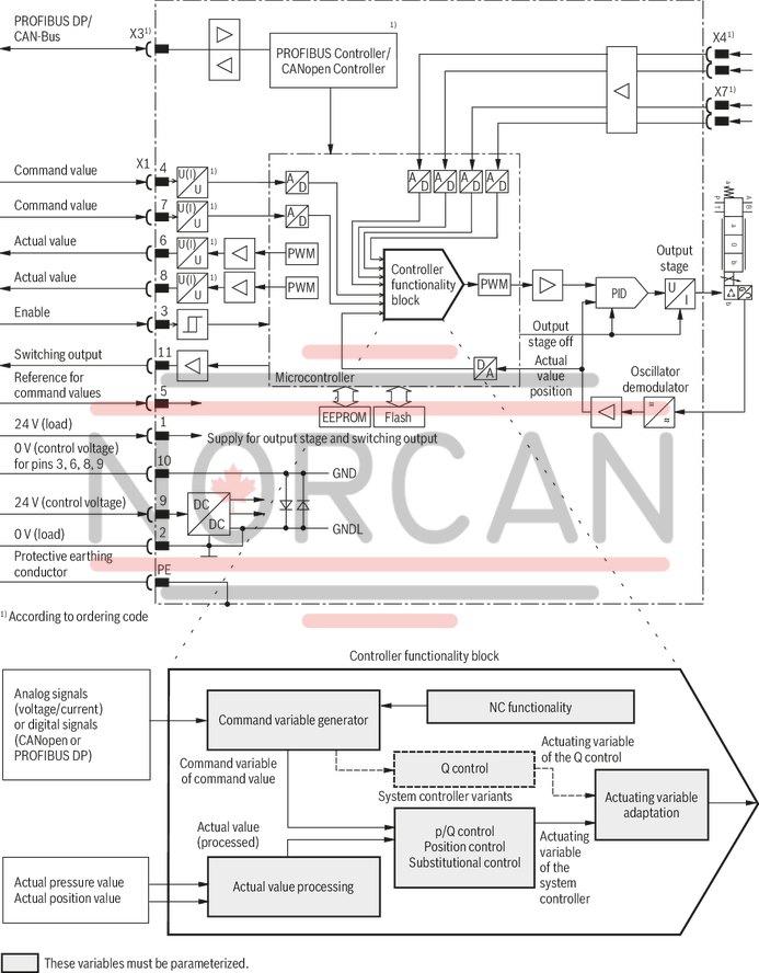
|
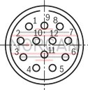
Connector pin assignment X1, 11-pole + PE according to EN 175201-804 |
|||
|
Pin |
Core marking 1) |
Assignment of interface A6 |
Assignment of interface F6 |
|
1 |
1 |
24 VDC (supply for output stage and power circuit signal) |
|
|
2 |
2 |
0 V ≙ load zero, (for output stage) |
|
|
3 |
3 |
Enable input 8.5 ... 24 VDC = function, Re ≈ 10 kΩ |
|
|
4 |
4 |
Command value ± 10 V; Re ≈ 130 kΩ or digital input (of PLC) 2) |
Command value 4 ... 20 mA; Re = 200 Ω or digital input (of PLC) 2) |
|
5 |
5 |
Reference for command values |
|
|
6 |
6 |
Actual value ±10 V |
Actual value 4 ... 20 mA, load resistance ≈ 330 Ωor digital output (at PLC) 2) |
|
7 |
7 |
Command value ± 10 V; Re ≈ 130 kΩ or digital input (of PLC) 2) |
Command value 4 ... 20 mA; Re = 200 Ω or digital input (of PLC) 2) |
|
8 |
8 |
Actual value ±10 V |
Actual value 4 ... 20 mA, load resistance ≈ 330 Ωor digital output (at PLC) 2) |
|
9 |
9 |
24 VDC (control voltage for signal part and bus) |
|
|
10 |
10 |
0 V reference potential for pins 3, 6, 8 and 9 |
|
|
11 |
11 |
Switching output 24 V (error signal or power circuit signal) max. 1.8 A |
|
|
PE |
green-yellow |
Protective earthing conductor (connected directly to metal housing) |
|
|
1) |
Core marking of the connection lines for mating connector with cable set |
||
|
2) |
Selection via commissioning software |
||
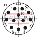
|
Connector pin assignment for CAN bus X3 (coding A), M12, 5-pole, pins |
|
|
Pin |
Assignment |
|
1 |
n.c. |
|
2 |
n.c. |
|
3 |
CAN_GND |
|
4 |
CAN_H |
|
5 |
CAN_L |
|
External screen on both sides at the plug-in connection metal housing Internal screens are not required |
|
|
Transmission rate kbit/s |
20 ... 1000 |
|
Bus address |
1 ... 27 |
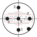
|
Connector pin assignment for Profibus DP X3, (coding B), M12, 5-pole, socket |
|
|
Pin |
Assignment |
|
1 |
VP |
|
2 |
RxD/TxD-N (A line) |
|
3 |
D_GND |
|
4 |
RxD/TxD-P (B line) |
|
5 |
Shield |
|
Transmission rate up to 12 MBaud |
|
|
Bus address |
1 ... 126 |
|
The galvanically isolated voltage +5 V (pin1-VP) at the socket enables passive termination of the Profibus |
|
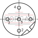
|
Analog sensor interfaces, port X4 and X7 (coding A), M12, 5-pole, socket |
||
|
Pin |
Assignment of voltage interface |
Assignment of current interface |
|
1 |
Supply 24 VDC |
Supply 24 VDC |
|
2 |
Signal 3 (X4) / 4 (X7), (-10 ... +10 V) |
Signal 3 (X4) / 4 (X7), (4 ... 20 mA) |
|
3 |
Zero 0 V |
Zero 0 V 1) |
|
4 |
Signal 1 (X4) / 4 (X7), (-10 ... +10 V) |
Signal 1 (X4) / 4 (X7), (4 ... 20 mA) |
|
5 |
Shield |
Shield |
|
1) |
Do not connect at 2-wire pressure transducer |
|
|
Attention: The analog sensor interfaces at ports X4 and X7 are not coded. Risk of confusion! The user must ensure correct wiring! |
||
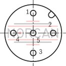
|
Digital sensor interface 1 Vpp or SSI measurement system X7, M23, 12-pole, socket |
||
|
Pin |
Assignment 1 Vpp |
Assignment SSI |
|
1 |
B |
0 V |
|
2 |
Sense +5 V 1) |
Data |
|
3 |
R |
Clock |
|
4 |
R |
n.c. |
|
5 |
A |
n.c. |
|
6 |
A |
n.c. |
|
7 |
n.c. |
n.c. |
|
8 |
B |
n.c. |
|
9 |
n.c. |
24 V |
|
10 |
0 V 1) |
Data |
|
11 |
Sense 0 V 1) |
Clock |
|
12 |
+5 V 1) |
n.c. |
|
Notice:The sense signal is not evaluated |
||
|
1) |
Recommendation:For encoder supply, connect voltages +5 V (pin 12) and +5 V sense (pin 2) as well as 0 V (pin 10) and 0 V sense (pin 11) |
|
|
Notice:We recommend connecting the shields on both sides via the metal housings of the plug-in connectors. Using connector pins will affect the effectiveness of the shielding effect! Internal screens are not required. |
||
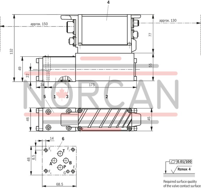
NG6
Dimensions in mm
|
1 |
Valve housing |
|
2 |
Control solenoid with position transducer |
|
3 |
Identical seal rings for ports A, B, P, and T |
|
4 |
Integrated digital control electronics |
|
5 |
Name plate |
|
6 |
Machined valve contact surface; Porting pattern according to ISO 4401-03-02-0-05 |
Recommended valve mounting screws (separate order):
4 hexagon socket head cap screws ISO 4762 - M5 x 30 - 10.9-N67F 821 70 (galvanized according to Bosch standard N67F 821 70)Tightening torque MA = 6+2Nm, material no. 2910151166
Size 10
Dimensions in mm
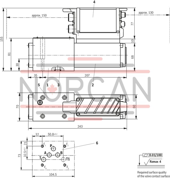
|
1 |
Valve housing |
|
2 |
Control solenoid with position transducer |
|
3 |
Identical seal rings for ports A, B, P and T (T1) |
|
4 |
Integrated digital control electronics |
|
5 |
Name plate |
|
6 |
Machined valve contact surface; Porting pattern according to ISO 4401-05-04-0-05 |
Recommended valve mounting screws (separate order):
4 hexagon socket head cap screws ISO 4762 - M6 x 40 - 10.9-N67F 821 70 (galvanized according to Bosch standard N67F 821 70)Tightening torque MA = 11+3 Nm, material no. 2910151209
Project planning and maintenance instructions
Connect the valve to the supply voltage only when this is required for the functional sequence of the machine. Do not use electrical signals provided via control electronics (e. g. "No error" signal) for switching safety-relevant machine functions (see also EN ISO 13849 "Safety of machinery – safety-related parts of control systems"). If electro-magnetic interference is to be expected, take appropriate measures ensuring the function (depending on the application, e. g. shielding, filtration). The devices have been tested in the plant and are supplied with default settings. Only complete devices can be repaired. Repaired devices are returned with default settings. User-specific settings will not be applied. The machine end-user will have to re-transfer the corresponding user parameters.Protective cap M12 with pin
Material number R901075564

Protective cap M12
Material number R901075563

Mating connectors for valves with round connector, 11-pole + PE
12P N11

Mating connectors for valves with round connector, 11-pole + PE
12P N11
For valves with round connector according to EN 175201-804, 11-pole + PEData sheet
Spare parts & repair