


BOSCH REXROTH
R901237594
$99.62 USD
- BOSCH REXROTH
- Material:R901237594
- Model:OD142078KK2000-VEDS-10A-4320
Quantity in stock: 0
The Bosch Rexroth OD142078KK2000-VEDS-10A-4320 (R901237594) is a high-performance screw-in cartridge valve designed for hydraulic applications requiring precise control of fluid flow. This direct-acting spool valve is capable of handling a maximum operating pressure of up to 350 bar (5076 psi) and can accommodate a maximum flow rate of 200 l/min (52.8 gpm). It features a CAAN cavity and is equipped with a GZ coil, which must be ordered separately. The OD142078KK2000-VEDS-10A-4320 valve is part of the VEDS product family, which falls under the solenoid-operated valves direct acting spool way position category. It offers reliable on/off actuation through its solenoid mechanism, ensuring consistent performance in various hydraulic systems. The valve operates with FKM sealing material for enhanced durability and chemical resistance. This particular model has four ports: T, A, P, and B, allowing for versatile connection options within hydraulic circuits. The control spool can be actuated by wet-pin DC solenoids and has an integrated manual override feature for manual operation in the absence of electrical power. Additionally, the solenoid coil can be rotated to suit different installation requirements. The valve's design incorporates both poppet and spool types within its construction, offering flexibility in application use. It supports various hydraulic fluids like HL and HLP types. With its robust design and direct pilot operation mode, this Bosch Rexroth screw-in cartridge valve ensures efficient control for hydraulic systems in demanding environments.
Unpacked Weight: 0.45 kg
General information
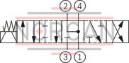
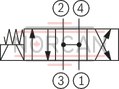
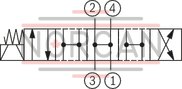
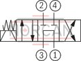
The 4/3 directional spool valves are direct operated, pressure-compensated screw-in cartridge valves. They control the start, stop and direction of flow and basically consist of pole tube (1), socket (2), a control spool (5) and a return spring (4).
Function
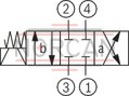
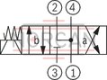
In the de-energized condition, the control spool (5) is held in the initial position by the return spring (4). The control spool (5) is actuated by wet-pin DC solenoids (3.1; 3.2). The symbols are realized by different spools (“10”; “20”; “40” and "60"). The main ports ➁, ➂ and ➃ can be pressurized continuously with an operating pressure of 350 bar. The ports have a fixed pin assignment (see Symbols). At port ➀, there may be a maximum pressure of 250 bar.
The manual override (6) allows for the switching of the valve without solenoid energization.
Version "C4"

Version "K4"

Version "K40"
Type VEDS-10A-43…
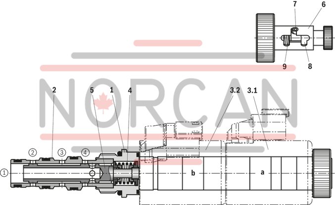
|
➀ |
Main port 1 (T) |
|
➁ |
Main port 2 (A) |
|
➂ |
Main port 3 (P) |
|
➃ |
Main port 4 (B) |
|
7 |
Initial position |
|
8 |
Spool position “a” |
|
9 |
Spool position “b” |
| Screw-in cartridge valve |
| Maximum operating pressure 350 bar (5000 psi) |
| Maximum flow 35 l/min (9,3 gpm) |
| Cavity CA-10A-4N |
| Max. pressure | 350 |
| Coil | GZ37 |
| Product family classification | Solenoid operated valves direct acting spool 4-way 3-position |
| Productgroup ID | 7,21,22,23,24,25 |
| Product family type | VEDS |
| Ports number | 4 |
| Type of actuation | Solenoid-actuated on/off |
| Sealing material | FKM |
| Cavity | CA-10A-4N |
| Product type | VEDS |
| Max. flow | 35 |
| Type of connection | Screw-in cartridge valve |
| Nominal flow | 35 |
| Direct - Pilot | Direct acting |
| Positions | 3 |
| Product family | 4 ways |
| Coil integrated | To be ordered separately |
| Spool Poppet | Spool type |
| Weight | 0.45 |
| Hydraulic fluid | HL,HLP |
(valve without coil)1)
|
01 |
02 |
03 |
04 |
05 |
06 |
07 |
08 |
09 |
10 |
11 |
12 |
|||
|
VEDS |
- |
10A |
- |
43 |
OD14 |
78 |
KK2 |
0 |
0 |
|
01 |
Directional spool valve, direct operated |
VEDS |
|
|
02 |
Frame size 10 |
10A |
|
|
03 |
4/3-way version |
43 |
|
|
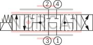
Symbols |
|||
|
04 |
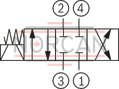
|
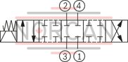
|
10 |
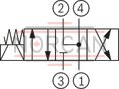
|
|
20 |
|
|
|
40 |
|
|
|
60 |
|
|
05 |
Without manual override |
0 |
|
|
With pull/push manual override |
-M1 |
||
|
06 |
4/3 directional spool valve, direct operated, with solenoid actuation |
OD14 |
|
|
Symbols |
|||
|
07 |
see item 04 |
10 |
|
|
20 |
|||
|
40 |
|||
|
60 |
|||
|
08 |
Frame size 10: R/UNF 10-04-0-06, see Installation bore |
78 |
|
|
09 |
On/off valves with 2 coils |
KK2 |
|
|
10 |
Without manual override |
0 |
|
|
With pull/push manual override |
1 |
||
|
11 |
Standard version |
0 |
|
|
12 |
Revision status |
0 |
|
| 1) Complete valves with mounted coil on request. | |
general
|
Size |
10 | ||
|
Weight |
Valve |
kg |
0.35 |
|
Coil |
kg |
0.25 | |
|
Installation position |
any - if it is ensured that no air can accumulate upstream of the valve. Otherwise, we recommend suspended installation of the valve | ||
|
Ambient temperature range 1) |
°C |
-40 … +110 | |
|
Storage temperature range |
°C |
-20 … +80 | |
| 1) | see voltage tolerance characteristic curve |
general (environmental audits)
|
Salt spray test according to DIN 50021 |
h |
720 |
|
Surface protection DC solenoids |
Coating according to DIN 50962-Fe//ZnNi with thick film passivation |
hydraulic
|
Size |
10 | ||
|
Maximum operating pressure |
bar |
350 | |
|
Port ➁ |
bar |
350 | |
|
Port ➂ |
bar |
350 | |
|
Port ➃ |
bar |
350 | |
|
Port ➀ |
bar |
250 | |
|
Maximum flow |
l/min |
35 | |
|
Zero flow 1) |
ml/min |
< 60 | |
|
Hydraulic fluid |
see table | ||
|
Hydraulic fluid temperature range |
°C |
-40 … +80 | |
|
Viscosity range 2) |
mm²/s |
5 … 1,000 | |
|
Maximum admissible degree of contamination of the hydraulic fluid 3) |
Class 20/18/15 according to ISO 4406 (c) | ||
|
Fatigue strength according to ISO 10771 |
2 million | ||
| 1) | With Δp = 250 bar; HLP46, ϑOil = 40 °C. |
| 2) | preferably 10 to 100 mm2/s |
| 3) | The cleanliness classes specified for the components must be adhered to in hydraulic systems. Effective filtration prevents faults and simultaneously increases the life cycle of the components. For the selection of the filters, see www.boschrexroth.com/filter. |
|
Hydraulic fluid |
Classification |
Suitable sealing materials |
Standards |
|
|
Mineral oils |
HL, HLP |
FKM |
DIN 51524 |
|
|
Bio-degradable |
Insoluble in water |
HEES |
FKM |
VDMA 24568 |
|
Soluble in water |
HEPG |
FKM |
||
|
Important information on hydraulic fluids! For further information and data on the use of other hydraulic fluids, please refer to data sheet 90220 or contact us! There may be limitations regarding the technical valve data (temperature, pressure range, life cycle, maintenance intervals, etc.)! The flash point of the hydraulic fluids used must be 40 K higher than the maximum solenoid surface temperature. Bio-degradable: If bio-degradable hydraulic fluids are used that are also zinc-solving, there may be an accumulation of zinc. |
||||
In the electrical connection, the protective earthing conductor (PE, grounded) is to be connected in accordance with the stipulations.
electrical
|
Voltage type |
Direct voltage | ||
|
Power supply 1) |
V |
12 24 |
|
|
Voltage tolerance against ambient temperature |
see voltage tolerance characteristic curve | ||
|
Power consumption |
W |
22 | |
|
Duty cycle |
% |
100 | |
|
Maximum coil temperature 2) |
°C |
150 | |
|
Switching time according to ISO 6403 |
ON |
ms |
≤ 80 |
|
OFF |
ms |
≤ 50 | |
|
Maximum switching frequency |
1/h |
15000 | |
|
Protection class according to DIN EN 60529 (VDE 0470-1), DIN 40050-9 |
Version "K4" |
IP65 (with mating connector mounted and locked) | |
|
Version "C4" |
IP66 with mating connector mounted and locked IP69K with Rexroth mating connector (material no. R901022127) |
||
|
Version "K40" |
IP69K with mating connector mounted and locked | ||
| 1) | Other voltages upon request |
| 2) | Due to the surface temperatures occurring at solenoid coils, the European standards ISO 13732-1 and ISO 4413 need to be adhered to. |
For applications outside these parameters, please consult us!
Voltage tolerance against ambient temperature; duty cycle
Voltage range and duty cycle dependent on the ambient temperature

(measured with HLP46, ϑoil = 40 ±5 °C) and 24 V coil
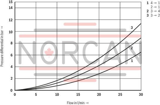
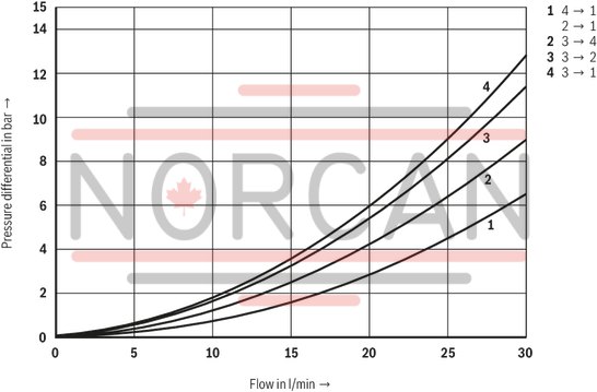
Δp-qV characteristic curves – Symbol “10”
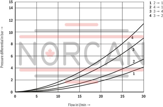
Δp-qV characteristic curves – Symbol “20”
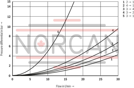
Δp-qV characteristic curves – Symbol “40”
Δp-qVcharacteristic curves – Symbol “60”
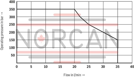
Performance limits (measured with HLP46, ϑOil = 40 ±5 °C)
Symbol “10” and “20”
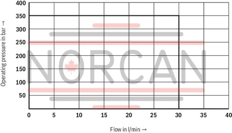
Symbol “40”
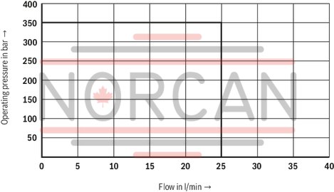
Symbol “60”
Attention!
The specified performance limits are valid for use with two directions of flow (e. g. from ➂ to ➁ and simultaneous return flow from ➃ to ➀). Due to the flow forces acting within the valves, the admissible performance limit may be considerably lower with only one direction of flow (e. g. from ➂ to ➁ while port ➃ is blocked)!
In such use cases, please consult us!
The performance limit was determined when the solenoids were at operating temperature, at 10 % undervoltage and without tank preloading.
Symbol “10”
Symbol “20”
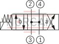
Symbol “60”

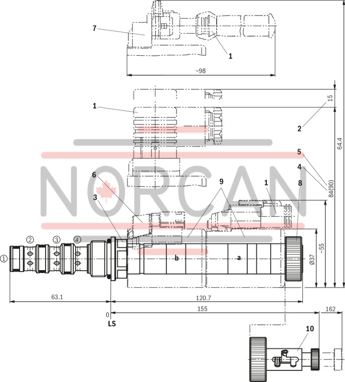
Dimensions in mm
|
1 |
Mating connectors (separate order) |
|
2 |
Space required to remove the mating connector |
|
3 |
Wrench size 24, tightening torque MA = 55+5 Nm |
|
4 |
Dimension for mating connector “K4”, without circuitry |
|
5 |
Dimension () for mating connector “K4”, with circuitry |
|
6 |
Version "K40" |
|
7 |
Version "C4" |
|
8 |
Nut, tightening torque MA = 5+1 Nm |
|
9 |
Coil (separate order, see type key) |
|
10 |
Pull/push manual override "1" |
|
➀ |
Main port 1 (T) |
|
➁ |
Main port 2 (A) |
|
➂ |
Main port 3 (P) |
|
➃ |
Main port 4 (B) |
|
LS |
Location shoulder |
Mounting cavity R/UNF-10-04-0-06; 4 main ports; thread 7/8-14UNF-2B
Dimensions in mm
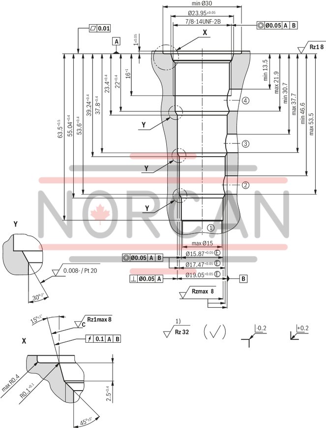
| 1) | Visual inspection |
|
➀ |
Main port 1 (T) |
|
➁ |
Main port 2 (A) |
|
➂ |
Main port 3 (P) |
|
➃ |
Main port 4 (B) |
|
LS |
Location shoulder |
|
Tolerance for all angles ± 0.5 ° |
|
|
All seal ring insertion faces are rounded and free of burrs |
|
Mating connectors for directional valves with connector "C4" and "C4Z" (AMP Junior-Timer), litz wire outer diameter 2.2 mm to 3.0 mm
2P JUNIOR D2 2
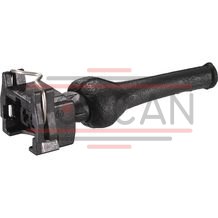
Mating connectors for directional valves with connector "C4" and "C4Z" (AMP Junior-Timer), litz wire outer diameter 2.2 mm to 3.0 mm
2P JUNIOR D2 2
For directional valves with connector "C4" and "C4Z" (AMP Junior-Timer)Data sheet
Spare parts & repair