

BOSCH REXROTH
R901252715
$457.26 USD
- BOSCH REXROTH
- Material:R901252715
- Model:KSDER0NA/BN11V
Quantity in stock: 0
The Bosch Rexroth KSDER0NA/BN11V (R901252715) is a high-performance directional poppet valve designed for hydraulic applications requiring precise control and reliability. This direct-operated, solenoid-actuated screw-in cartridge valve is engineered to deliver leak-free blocking of flow with its poppet-type spool. The KSDER0NA/BN11V operates at a maximum pressure of up to 350 bar (5076 psi) and is capable of handling a maximum flow rate of 80 l/min (21 gpm), making it suitable for a wide range of demanding applications. The valve features a manual override option, enabling operators to actuate the valve manually without solenoid energization. This is particularly useful during maintenance or emergency situations. The manual override comes in two versions: concealed and screw type, providing additional flexibility for various operational requirements. Designed with FKM sealing material, the KSDER0NA/BN11V offers excellent compatibility with different types of hydraulic fluids such as HL, HLP, HETG, HEPG, and HEES. Its robust construction ensures reliable switching performance even after extended periods of non-operation. Furthermore, the wet-pin DC solenoids are designed for durability and can be rotated to facilitate ease of installation. With its normally closed configuration and two different mounting cavities (RB or RC), this directional seat valve offers versatility for integration into diverse hydraulic systems. The compact design allows for efficient use of space without sacrificing functionality or performance. In summary, the Bosch Rexroth KSDER0NA/BN11V is an advanced screw-in cartridge valve that provides secure and pressure-compensated control in hydraulic systems. Its solid construction, manual override feature, compatibility with various fluids, and reliable operation make it an essential component for industrial applications requiring precise fluid control.
2/2 directional poppet valve, direct operated with solenoid actuation
Unpacked Weight: 0.28 kg
General
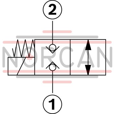
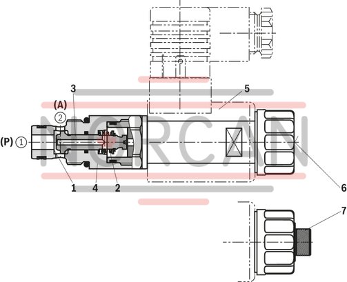
The 2/2 directional seat valves are direct operated, pressure-compensated screw-in cartridge valves. They basically consist of a screw-in section (4) with valve seat (1), solenoid (5) as well as closing element (3) and compression spring (2).
Function
The initial position of the valve (normally open "P" or normally closed "N") is determined by the position of the closing element (3) and the arrangement of the compression spring (2). Due to the structural design, the 2/2 directional seat valves are always pressure-compensated in relation to the actuating forces. The main ports ➀ and ➁ can be loaded with an operating pressure of 350 bar (see Technical data).
At symbol "P", the closing element (3) is pressed onto the seat by the solenoid (5), with symbol "N" by the compression spring (2). The flow is blocked in a leak-free manner.
The manual override allows for the switching of the valve without solenoid energization. It is available in concealed version "N9" (6) or in screwable version "N11" (7) (see ordering codes).
The screwable manual override (7) is to be screwed back into the initial position after actuation.
Version "K4" (with mating connector)
Type KSDER0PA/BN0V
Version "C4"
Version "K40"
| Screw-in cartridge valve |
| Maximum operating pressure 350 bar (5000 psi) |
| Maximum flow 20 l/min (5 gpm) |
| Cavity M20x1.5 |
| Max. pressure | 350 |
| Coil | GZ37 |
| Product family classification | 2/2 directional poppet valve, direct operated with solenoid actuation |
| Productgroup ID | 9,10,11,12,13,14 |
| Product family type | KSDE |
| Ports number | 2 |
| Manual override | Screw type manual override |
| Type of actuation | Solenoid-actuated on/off |
| Sealing material | FKM |
| Cavity | M20x1.5 |
| Product type | KSDE |
| Max. flow | 20 |
| Type of connection | Screw-in cartridge valve |
| Normal position | Normally closed |
| Nominal flow | 20 |
| Direct - Pilot | Direct acting |
| Positions | 2 |
| Product family | 2 ways |
| Coil integrated | To be ordered separately |
| Spool Poppet | Poppet type |
| Weight | 0.28 |
| Hydraulic fluid | HL,HLP,HETG,HEPG,HEES |
(valve without coil) 1)
|
01 |
02 |
03 |
04 |
05 |
06 |
07 |
08 |
09 |
|
|
KSDE |
R |
0 |
A |
/ |
V
|
* |
|
01 |
Directional seat valve, direct operated, electrically operated |
KSDE |
||||
|
02 |
Maximum operating pressure 350 bar |
R |
||||
|
03 |
Component size |
0 |
||||
|
04 |
2 main ports |
|||||
|
Symbols |
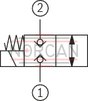
|
Normally closed |
N |
|||
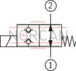
|
Normally open |
P |
||||
|
05 |
Component series |
A |
||||
|
06 |
High Performance and mounting cavity R/B (see Mounting cavity) |
B |
||||
|
High Performance and mounting cavity R/C (see Mounting cavity) |
C |
|||||
|
07 |
Without manual override |
N0 |
||||
|
With concealed manual override |
N9 |
|||||
|
With screwable manual override |
N11 |
|||||
|
Symbol N |
Symbol P |
|||||
|
N0 |
N9 |
N11 |
N0 |
N9 |
N11 |
|
|
X |
– |
X |
X |
X 2) |
– |
|
|
Seal material |
||||||
|
08 |
FKM seals (other seals upon request) |
V |
||||
|
Observe compatibility of seals with hydraulic fluid used. |
||||||
|
09 |
Further details in the plain text |
* |
||||
| 1) Complete valves with mounted coil available on request | |
| 2) Screwable manual override “N10” (actuation by means of internal hexagon with lock nut), possible as separate order, material no. R901051231; ordering code “N9” ! |
general
|
Size |
0 | ||
|
Weight |
Valve |
kg |
0.3 |
|
Coil |
kg |
0.25 | |
|
Installation position |
any | ||
|
Ambient temperature range |
°C |
-40 … +110 | |
hydraulic
|
Size |
0 | ||
|
Maximum operating pressure |
bar |
350 | |
|
Maximum flow 1) |
l/min |
20 | |
|
Hydraulic fluid |
see table | ||
|
Hydraulic fluid temperature range |
°C |
-40 … +80 | |
|
Viscosity range |
mm²/s |
5 … 1,000 | |
|
Ideal |
mm²/s |
10 … 100 | |
|
Maximum admissible degree of contamination of the hydraulic fluid, cleanliness class according to ISO 4406 (c) 2) |
Class 20/18/15 according to ISO 4406 (c) | ||
|
Load cycles |
million |
10 | |
| 1) | See performance limits |
| 2) | The cleanliness classes specified for the components must be adhered to in hydraulic systems. Effective filtration prevents faults and simultaneously increases the life cycle of the components. For the selection of the filters, see www.boschrexroth.com/filter. |
|
Hydraulic fluid |
Classification |
Suitable sealing materials |
Standards |
|
|
Mineral oil |
HL, HLP |
FKM, NBR |
DIN 51524 |
|
|
Bio-degradable |
Insoluble in water |
HEES (synthetic esters) |
FKM |
VDMA 24568 |
|
HETG (rape seed oil) |
FKM, NBR |
|||
|
Soluble in water |
HEPG (polyglycols) |
FKM |
VDMA 24568 |
|
|
Other hydraulic fluids on request |
||||
electrical
|
Voltage type |
Direct voltage | ||
|
Power supply 1) |
V |
12 24 |
|
|
Voltage tolerance against ambient temperature |
See characteristic curves | ||
|
Power consumption |
W |
22 | |
|
Duty cycle |
% |
100 | |
|
Maximum coil temperature 2) |
°C |
150 | |
|
Switching time according to ISO 6403 (solenoid horizontal) |
ON (➀ → ➁) |
ms |
≤ 95 |
|
OFF (➁ → ➀) |
ms |
≤ 95 | |
|
Maximum switching frequency |
Version |
Hz |
9000 |
|
Protection class according to DIN EN 60529 |
Version "K4" |
IP65 (with mating connector mounted and locked) | |
|
Version "C4" |
IP66 with mating connector mounted and locked IP69K with Rexroth mating connector (material no. R901022127) |
||
|
Version "K40" |
IP69K with mating connector mounted and locked | ||
| 1) | Other voltages upon request |
| 2) | Due to the surface temperatures of the solenoid coils, the standards ISO 13732-1 and EN 982 need to be adhered to! |
With the electrical connection "K4", the protective earthing conductor (PE) is to be connected appropriately.
For applications outside these parameters, please consult us!
Voltage tolerance against ambient temperature; duty cycle
Voltage range and duty cycle dependent on the ambient temperature
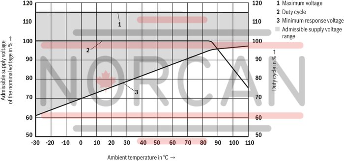
(measured with HLP46, ϑoil = 40 ±5 °C) and 24 V coil
Δp-qV characteristic curves
(measured with HLP46, ϑOil = 40 °C ± 5 °C) and 24 V coil
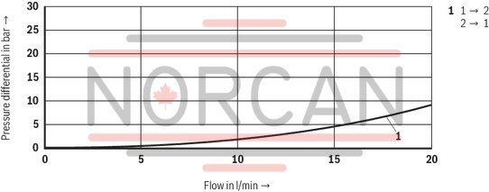
Performance limits (measured with HLP46, ϑOil = 40 ±5 °C and 24 V coil)
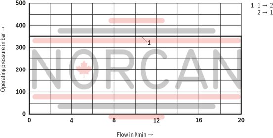
Attention!
The performance limit has been determined with the solenoids at operating temperature and with 10 % undervoltage.
Symbol “N” normally closed
Symbol “P” normally open
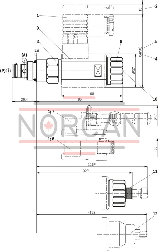
Dimensions in mm
|
1 |
Mating connector (separate order, see data sheet 08006) |
|
2 |
Space required to remove the mating connector |
|
3 |
SW24, tightening torque MA = 25 +5 Nm |
|
4 |
Dimension for mating connector “K4”, without circuitry |
|
5 |
Dimension () for mating connector “K4”, with circuitry |
|
6 |
Version "K40" |
|
7 |
Version "C4" |
|
8 |
Nut, tightening torque MA = 5+1 Nm |
|
9 |
Coil (separate order, see type key) |
|
10 |
Concealed manual override "N9", optional |
|
11 |
Screwable manual override "N11", optional |
|
12 |
Screwable manual override “N10” (separate order) |
|
➀ |
Main port 1, pump P 3) |
|
➁ |
Main port 2, actuator A 3) |
|
LS |
Location shoulder |
| 1) Actuated | |
| 2) Screwed in | |
| 3) Attention! | |
| Unambiguous pin assignment. P and A must not be exchanged or closed! |
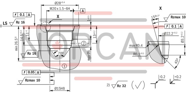
Mounting cavity, 2 main ports; M20 x 1.5 thread
Version "B"
Dimensions in mm
Mounting cavity, 2 main ports; M20 x 1.5 thread
Version "C"
Dimensions in mm
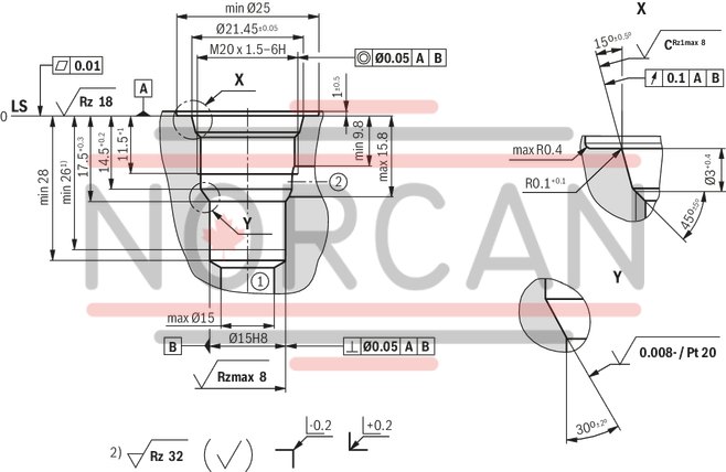
1) Depth of fit
2) Visual inspection
|
➀ |
Main port 1 |
|
➁ |
Main port 2 |
|
LS |
Location shoulder |
|
All seal ring in sertion faces are rounded and free of burrs; tolerance for all angles ± 0.5° |
|
Mating connectors for directional valves with connector "C4" and "C4Z" (AMP Junior-Timer), litz wire outer diameter 2.2 mm to 3.0 mm
2P JUNIOR D2 2
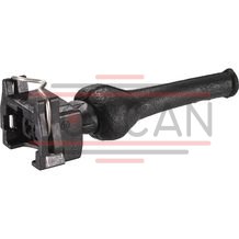
Mating connectors for directional valves with connector "C4" and "C4Z" (AMP Junior-Timer), litz wire outer diameter 2.2 mm to 3.0 mm
2P JUNIOR D2 2
For directional valves with connector "C4" and "C4Z" (AMP Junior-Timer)Data sheet
Spare parts & repair
Mating connectors for directional valves with connector "K40" (Deutsch plug)
2P DT06 K40
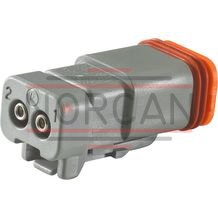
Mating connectors for directional valves with connector "K40" (Deutsch plug)
2P DT06 K40
For directional valves with "K40" connector (Deutsch plug)Data sheet
Spare parts & repair