


BOSCH REXROTH
R901276261
- BOSCH REXROTH
- Material:R901276261
- Model:HED 2 OA3X/400K6L24
Due to extremely high demand, please call 877-366-7226 for availability
The Bosch Rexroth HED 2 OA3X/400K6L24 (R901276261) is a high-quality pressure switch designed for precision monitoring and control in hydraulic systems. This model features an optional control lamp for easy status indication and can be connected electrically via a cable gland or connector, providing flexibility for various installation requirements. The lockable rotary knob ensures secure settings, preventing accidental adjustments that might occur in demanding environments. With its component series X, the HED 2 OA3X/400K6L24 is built to withstand maximum operating pressures up to 400 bar, making it suitable for use in applications with high-pressure demands. It offers pressure ratings at intervals of 50, 100, 200, 315, and 400 bar to cater to a broad range of hydraulic system requirements. The versatility of this pressure switch makes it an essential component for ensuring the safety and efficiency of hydraulic operations. Furthermore, this model from Bosch Rexroth has been CCC certified, attesting to its compliance with international safety standards. Its robust construction and reliable performance make it a preferred choice for maintaining precise control over hydraulic pressures in various applications. Whether used in industrial machinery or mobile equipment, the HED 2 OA3X/400K6L24 pressure switch is engineered to deliver consistent results and enhance system functionality.
|
01 |
02 |
03 |
04 |
05 |
06 |
|
|
HED 2 OA |
3X |
/ |
* |
|
01 |
Bourdon tube pressure switch |
HED 2 OA |
|
02 |
Component series 30 ... 39 (30 ... 39: unchanged installation and connection dimensions) |
3X |
|
03 |
Pressure rating maximum 25 bar |
25 |
|
Pressure rating maximum 63 bar |
63 |
|
|
Pressure rating maximum 100 bar |
100 |
|
|
Pressure rating maximum 200 bar |
200 |
|
|
Pressure rating maximum 400 bar |
400 |
|
|
Electrical connection |
||
|
04 |
Cable gland |
no code |
|
Connector 6-pole + PE |
K6 1) |
|
|
05 |
without control lamp |
no code |
|
Control lamp for 24V (20V to 35V) |
L24 |
|
|
06 |
Further details in the plain text |
|
| 1) Mating connectors, separate order, see below. |
Type
|
Component series |
3X |
General
|
Weight |
m |
kg |
1 | |
|
Installation position |
any | |||
|
Ambient temperature ranges (NBR seals) |
ϑ |
°C |
-30 … +50 | |
|
Conformity/certification |
CE |
EN 61058-1:1993, IEC 60947-5-1 | ||
Hydraulisch
|
Pressure rating |
p |
bar |
25 | 63 | 100 | 200 | 400 |
|
Max. operating pressure 1) |
p |
bar |
30 | 70 | 110 | 210 | 420 |
|
Switching pressure differential |
p |
bar |
1 | 2 | 2.5 | 5 | 7.5 |
|
Pressure adjustment range (decreasing) |
p |
bar |
8 … 25 | 4 … 63 | 6 … 100 | 10 … 200 | 20 … 400 |
|
Pressure adjustment range (increasing) |
p |
bar |
2.5 … 26 | 6 … 66 | 8.5 … 102.5 | 15 … 205 | 27.5 … 407.5 |
|
Hydraulic fluid temperature range (NBR seals) |
ϑ |
°C |
-30 … +80 | ||||
|
Viscosity range |
μ |
mm²/s |
10 … 800 | ||||
|
Maximum admissible degree of contamination of the hydraulic fluid 2) |
Class 20/18/15 according to ISO 4406 (c) | ||||||
| 1) | short-time |
| 2) | The cleanliness classes specified for the components must be adhered to in hydraulic systems. Effective filtration prevents faults and simultaneously increases the life cycle of the components. For the selection of the filters, see www.boschrexroth.com/filter. |
Elektrisch
|
Anschlussart |
Cable gland Pg 11; connector Pg 11 | |||
|
Protection class according to DIN EN 60529 |
IP65 (with mating connector mounted and locked) | |||
|
Line cross-section |
Mating connector, max. |
mm² |
1.5 | |
|
Cable gland, max. |
mm² |
1.5 | ||
|
Switching frequency, max. |
1/h |
1800 | ||
|
Switching accuracy (repetition accuracy) |
± 1 % of the set pressure | |||
|
Contact load |
AC voltage |
I |
250 V; 3 A | |
|
Direct voltage |
I |
40 V; 1 A; In case of DC voltage with inductive load, spark extinguishing is to be provided in order to increase the life cycle. | ||
|
Long-term drift of the switching points |
50,000 load cycles 1) |
+5 % of the maximum set pressure | ||
|
100,000 load cycles |
+10 % of the maximum set pressure | |||
| 1) | With more than 100000 load cycles, no statements with regard to a long-term drift can be made. |
For applications outside these parameters, please consult us!
Mating connectors for mechanical position switches, mechanical pressure switches and valves with central connection with connector “K6” and “DK6L”, 6-pole + PE
7P Z6
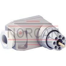
Mating connectors for mechanical position switches, mechanical pressure switches and valves with central connection with connector “K6” and “DK6L”, 6-pole + PE
7P Z6
Mating connectors for mechanical position switches, mechanical pressure switches and valves with central connection with connector “K6”Data sheet
Spare parts & repair