

BOSCH REXROTH
R901288142
- BOSCH REXROTH
- Material:R901288142
- Model:VT-MSPA1-150-1X/V0/0
Due to extremely high demand, please call 877-366-7226 for availability
The Bosch Rexroth VT-MSPA1-150-1X/V0/0 (R901288142) is an analog amplifier designed for the precise control of pressure valves without electrical feedback. This device features a modular construction that facilitates easy installation on standard top hat rails typically found in control cabinets. It operates with standard command value signals ranging from 0 to 10 V, and includes a zero point potentiometer (Zw) for correcting any zero point offset. The VT-MSPA1-150-1X/V0/0 also comes equipped with a ramp generator that limits the slope of the control output signal. The ramp times for both increasing and decreasing command value signals can be adjusted independently using the trimmers t< and t>, respectively. Furthermore, the characteristic curve generator allows users to set the rated current for the solenoid using trimmer Gw, ensuring a linear relationship between command value signals and current. Additionally, this model includes a clock generator that determines the frequency of the output stage based on the command value signal. The power output stage then produces a PWM signal in accordance with this frequency and the input from the characteristic curve generator, which is then supplied to the solenoid. The solenoid current is continuously monitored and any discrepancies are corrected by the current controller. For added reliability, Bosch Rexroth's VT-MSPA1-150-1X/V0/0 has built-in fault recognition capabilities that monitor for cable breaks, short circuits, or overcurrent conditions in the solenoid conductors. Any detected errors result in deactivation of the green "ready for operation" LED indicator. Additional features include differential input for voltage ramp generation with adjustable ramp times up/down, adjustable zero point and sensitivity settings, dither generation capability, as well as reverse polarity protection for operating voltage to ensure safe operation at all times.
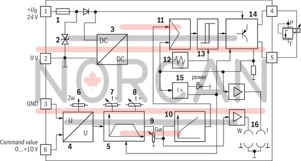
Analog amplifier for controlling pressure valves without electrical feedback. The modular design allows for simple top hat rail mounting as is usual in control cabinets.
Command value input [4]
The module amplifier is controlled by means of a standard command value signal 0 to +10 V. By means of the zero point potentiometer (Zw) [6], a zero point offset can be corrected.
Ramp generator [5]
In the ramp generator [5], the control output incline is limited. Using the trimmer "t <" [7], the time for the increasing command value signal is set and using trimmer "t >" [8], the time for the decreasing command value voltage is set.
Characteristic curve generator [10]
Using the trimmer "Gw" [9], the rated current for the solenoid is set. In the characteristic curve generator [10], the command value signal is changed so that a linear command value current characteristic curve is created.
Clock generator [12]
In the clock generator [12], a frequency for the output stage adjusted to the command value is generated.
Power output stage [11]-[14]
Using the control output coming from the characteristic curve generator [10] and the clock frequency, the power output stage generates a PWM signal that is fed into the solenoid. The solenoid current is recorded and, in the current controller [11], compared with the control output and the difference is compensated.
Fault recognition [15]
Monitors the solenoid conductors with reference to cable break and short-circuit as well as over-current of the output stage. If there is an error, the green ready for operation display goes out.
|
01 |
02 |
03 |
04 |
05 |
||||
|
VT-MSPA1 |
‒ |
150 |
‒ |
1X |
/ |
V0 |
/ |
* |
|
01 |
Valve amplifier for proportional valves without electrical position feedback, Analog, Modular design |
VT-MSPA1 |
|
02 |
For valves: |
150 |
|
03 |
Component series 10 ... 19 (10 ... 19: unchanged installation and connection dimensions) |
1X |
|
04 |
Version: standard |
V0 |
|
05 |
Further details in the plain text |
* |
General
|
Component series |
1X | |
|
Type of electronics |
Analog | |
|
Design |
Modul |
Voltage supply
|
Operating voltage |
nominal |
U |
V |
24 |
|
Lower limit value |
UB(t)min |
V |
21 | |
|
Upper limit value |
UB(t)max |
V |
35 | |
|
Power consumption |
max. |
Smax |
VA |
25 |
|
Current consumption |
max. |
Imax |
A |
1 |
|
Fuse |
Electronic overload protection and SMD fuse (soldered in) | |||
Analog inputs
|
Command value |
Voltage (differential input) |
U |
V |
0 ... 10 | |
|
Voltage (differential input) |
Input resistance |
R |
kΩ |
≥ 100 | |
Solenoid outputs
|
Pilot current |
Factory setting |
Iv |
mA |
200 |
|
Solenoid current |
max. |
Imax |
A |
0.7 |
|
Coil resistance at 20°C |
R(20) |
Ω |
19.5 | |
|
Clock frequency |
Factory setting |
f |
Hz |
100 ±10 % |
|
Solenoid output |
other properties |
Short-circuit-proof, clocked | ||
Adjustment options
|
Solenoid current |
I |
A |
0.2 ... 0.7 |
|
Zero point calibration |
% |
± 25 | |
|
Ramp time up/down |
t |
s |
0.06 … 5 |
Measuring sockets
|
Command value |
"w" |
U |
V |
0 ... 10 | |
|
Actual current value |
"I" |
U |
V |
0 ... 0.7 (mV ≙ mA) | |
Displays
|
LED display |
Green |
Ready for operation |
Supplementary information
|
Anschlussart |
6 screw terminals | ||
|
Mounting type |
Top hat rail TH 35-7.5 according to EN 60715 | ||
|
Type of protection according to EN 60529 |
IP 20 | ||
|
Ambient temperature range |
ϑ |
°C |
0 … 50 |
|
Storage temperature range |
ϑ |
°C |
-25 … 85 |
|
Weight |
m |
kg |
0.15 |
For applications outside these parameters, please consult us!
Notice:
For information on the environment simulation testing for the areas of EMC (electro-magnetic compatibility), climate and mechanical load, see data sheet 30223-U.
Output characteristic curve


Measuring sockets
|
Command value |
|
|
Actual current value (mV ≙ mA) |
|
|
Reference potential |
Potentiometer
|
Gw |
Amplitude attenuator |
|
Zw |
Zero point |
|
t < |
Ramp time "Ramp up" |
|
t > |
Ramp time "Ramp down" |
|
Fuse |
|
|
Suppressor diode |
|
|
Power supply unit |
|
|
Voltage input |
|
|
Ramp generator |
|
|
Zero point setting |
|
|
Ramp time "Ramp up" |
|
|
Ramp time "Ramp down" |
|
|
Command value attenuator |
|
|
Characteristic curve generator |
|
|
Current controller |
|
|
Clock generator |
|
|
Schmitt trigger |
|
|
Clocked output stage |
|
|
Fault recognition |
|
|
Measuring sockets |
3/2 directional seat valve – version "CK"
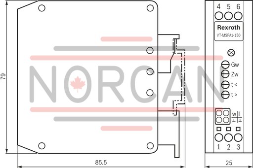
Dimensions in mm

Dimensions in mm
The amplifier module may only be wired when de-energized.
The distance to radios must be sufficient (>> 1 m).
Shield command value lines, do not lay them close to power cables, screen solenoid conductors.
Do not use free-wheeling diodes in the solenoid conductors.
With a strongly fluctuating operating voltage, it may in individual cases be necessary to use an external smoothing capacitor with a capacity of at least 2200 µF.
Recommendation: Capacitor module VT 11110 (see data sheet 30750); sufficient for up to 3 amplifier modules.