


BOSCH REXROTH
R901318756
$10,850.29 USD
- BOSCH REXROTH
- Material:R901318756
- Model:VT-DFPN-A-2X/G24K0/0R0V/V
Quantity in stock: 0
The Bosch Rexroth VT-DFPN-A-2X/G24K0/0R0V/V (R901318756) is a highly specialized pilot valve designed to provide precise pressure and flow control within the SYHDFE system. This advanced component is engineered to operate through a proportional solenoid that includes electrical feedback, ensuring high levels of accuracy and responsiveness in system regulation. The control electronics of this pilot valve are integrated and digital, featuring a CAN bus interface which facilitates variable-speed operation—a critical function for optimizing energy consumption and system efficiency. With its maximum operating pressure capability, the VT-DFPN-A-2X/G24K0/0R0V/V is built to withstand demanding conditions while delivering consistent performance. This makes it an ideal solution for applications requiring exacting control of hydraulic pressure and flow rates. Its robust design and precision engineering are indicative of Bosch Rexroth's commitment to quality in components that are integral to complex hydraulic systems. The product's capabilities extend to its compatibility with the Sytronix DFEn and SYHDFEn systems, highlighting its versatility in different setups within the same family of control systems. It is particularly suited for scenarios where precise electronic regulation is necessary for optimized system operation. The inclusion of a CAN bus interface underscores the product's readiness for integration into modern industrial environments where communication between devices is essential for coordinated operation. In summary, the Bosch Rexroth VT-DFPN-A-2X/G24K0/0R0V/V is an advanced pilot valve designed for meticulous management of pressure and flow in hydraulic systems, demonstrating both flexibility and resilience in industrial applications.
|
01 |
02 |
03 |
04 |
05 |
06 |
07 |
08 |
09 |
10 |
11 |
||||||
|
VT-DFPn |
- |
- |
2X |
/ |
G24 |
K0 |
/ |
0 |
/ |
- |
* |
|
Series |
|||||||
|
01 |
Pilot valve with integrated digital electronics, variable-speed |
VT-DFPn |
|||||
|
Spool design |
|||||||
|
02 |
Standard (not for HFC fluids) |
A |
|||||
|
2-groove spool (only for replacement requirement) |
B |
||||||
|
4-groove spool (e.g. for HFC fluids) |
C |
||||||
|
03 |
Component series |
2X |
|||||
|
04 |
Direct voltage 24 V |
G24 |
|||||
|
05 |
Connector (without mating connector) 1) |
K0 |
|||||
|
Installation orientation connector (VT-DFP) and/or integrated electronics (see also comment on feature 6) |
|||||||
|
06 |
radially to the pump axis |
0 |
|||||
|
folded 90° in the direction of the subplate with counterclockwise direction of rotation |
1 |
||||||
|
folded 90° in the direction of the subplate with clockwise direction of rotation |
2 |
||||||
|
Additional functions: Closed-loop control |
A |
B |
C |
D |
R |
||
|
07 |
Teach-in version for cyclic operation |
● |
A |
||||
|
Real-time version (speed calculation without teach-in) |
● |
R |
|||||
|
Electronics assembly, option |
|||||||
|
08 |
Standard |
● |
0 |
||||
|
Actual pressure value input |
Plug-in connector |
||||||
|
09 |
Current input 4...20 mA |
X1 |
C |
||||
|
Voltage input 0...10 V (standard) |
X1 |
V |
|||||
|
Voltage input 1...10 V |
X1 |
E |
|||||
|
Voltage input 0.5..5 V (Standard) 2) |
X2 |
F |
|||||
|
10 |
FKM seals suitable for mineral oils (HL, HLP) according to DIN 51524 and HFC fluids 3) |
V |
|||||
|
11 |
Further details in the plain text e. g. SO variant |
* |
|||||
|
1 |
Material number |
|
2 |
Serial number |
|
3 |
Date of production |
|
4 |
Production order number |
|
5 |
Type designation |
|
● |
available |
|
- |
not available |
Note on feature 6: Installation orientation of the valve electronics
|
Clockwise direction of rotation, installation orientation 0 |
Clockwise direction of rotation, installation orientation 2 |
Counterclockwise direction of rotation, installation orientation 0 |
Counterclockwise direction of rotation, installation orientation 1 |

|

|

|

|
| 1) | Connector dependent on the valve type (see "Technical data" and "Electrical connection”). |
| 2) | With the SY(H)DFEn control system with analog interfaces, the plug-in connector X2 can not be used as actual pressure value input. Thus, a separate pressure transducer has to be used and connected to plug-in connector X1 in this case. |
| 3) | Only in connection with SYHDFE and spool design C (feature 2). |

|
1 |
Material number |
|
2 |
Serial number |
|
3 |
Date of production |
|
4 |
Production order number |
|
5 |
Type designation |
|
● |
available |
|
- |
not available |
Accessories
Version 10/2011, enquire availability
|
Accessories |
Material number |
Data sheet |
|
Mating connector 12-pole for central connection X1 without cable (assembly kit) |
R900884671 |
08006 |
|
Mating connector 12-pole for central connection X1 with cable set 2 x 5 m |
R900032356 |
|
|
Mating connector 12-pole for central connection X1 with cable set 2 x 20 m |
R900860399 |
|
|
Test device VT-PDFE-1-1X/V0/0 for SY(H)DFEE and SY(H)DFEC |
R900757051 |
29689-B |
|
Compact power supply unit VT-NE32-1X |
R900080049 |
29929 |
|
Converter USB serial for laptops without serial interface VT-ZKO-USB/S-1-1X/V0/0 |
R901066684 |
|
|
Cable for the connection of a Win-PED PC (RS232) at the interface X2, length 3 m |
R901156928 |
|
|
T connector for the simultaneous connection of a WIN-PED PC (RS232) and use of the input at connector X2 |
R901117164 |
|
|
Mating connector for interface X3, M12, straight, can be connected independently, 5-pole, shielded, A coded, cable diameter 6 ... 8 mm |
R901076910 |
Notice:
For information on the environment simulation testing for the areas of EMC (electro-magnetic compatibility), climate and mechanical load, see data sheet 30030-U.
mechanic and hydraulic
|
Mass |
Pump without through-drive incl. pilot valve |
m |
kg |
2.25 |
|
Hydraulic fluid |
Mineral oil (HL, HLP) according to DIN 51524; HFC fluids only in connection with SYHDFE control system and C spool design C (feature 2 of ordering code) | |||
|
Hydraulic fluid temperature range |
ϑ |
°C |
-20 … +70 | |
|
Maximum admissible degree of contamination of the hydraulic fluid according to ISO 4406 |
Class 18/16/13 (for particle size ≤ 4/6/14 μm) | |||
mechanic and hydraulic
|
Weight without filling quantity |
m |
kg |
2.25 |
|
Hydraulic fluid |
Mineral oil (HL, HLP) according to DIN 51524; HFC fluids only in connection with SYHDFE control system and C spool design C (feature 2 of ordering code) | ||
|
Hydraulic fluid temperature range |
ϑ |
°C |
-20 … +70 |
|
Maximum admissible degree of contamination of the hydraulic fluid according to ISO 4406 |
Class 18/16/13 (for particle size ≤ 4/6/14 μm) | ||
electrical
|
Operating voltage |
UB |
24 VDC +40 % –5 % | ||
|
Operating range (short-time operation) |
Upper limit value |
UB(t)max |
V |
35 |
|
Lower limit value |
UB(t)min |
V |
21 | |
|
Current consumption (in static control operation) |
Rated current |
Inom |
A |
0.6 |
|
Maximum current |
Imax |
A |
1.25 | |
|
Inputs |
Actual pressure value input X1; |
U or I |
parameterizable: 0 ... 20 mA; 4 ... 20 mA; 0 ... 10 V; 0 … 5 V; 0.5 … 5 V; 0.1 ... 10 V; 1 ... 10 V | |
|
Analog current inputs, load |
RB |
100 Ω | ||
|
Analog voltage inputs |
RE |
≥ 100 kΩ | ||
|
Digital inputs |
Logic 0 |
≤ 8 V | ||
|
Logic 1 |
≥ 14 V | |||
|
Outputs |
pactual / UOUT1 |
UO 1) |
± 10 V | |
|
Imax 1) |
2 mA | |||
|
αactual / UOUT2 |
UO 1) |
± 10 V | ||
|
Imax 1) |
2 mA | |||
|
Digital outputs |
Logic 0 |
Ua < 1 V | ||
|
Logic 1 |
Ua ≥ UB – 5 V; 10 mA (short-circuit-proof) | |||
|
Ambient temperature range at the pump |
ϑ |
°C |
0 … +50 | |
|
Storage temperature range (pump + electronics) |
ϑ |
°C |
0 … +70 | |
|
Type of protection according to EN 60529 |
Pump incl. pilot valve |
IP65 with mounted and locked plug-in connectors | ||
| 1) | The outputs are parameterizable, for the condition as supplied, see electrical connection |
mechanisch und hydraulisch
|
Weight without filling quantity |
m |
kg |
2.25 |
|
Hydraulic fluid |
Mineral oil (HL, HLP) according to DIN 51524; HFC fluids only in connection with SYHDFE control system and C spool design C (feature 2 of ordering code) | ||
|
Hydraulic fluid temperature range |
ϑ |
°C |
-20 … +70 |
|
Maximum admissible degree of contamination of the hydraulic fluid according to ISO 4406 |
Class 18/16/13 (for particle size ≤ 4/6/14 μm) | ||
elektrisch
|
Operating voltage |
UB |
24 VDC +40 % –5 % | ||
|
Operating range (short-time operation) |
Upper limit value |
UB(t)max |
V |
35 |
|
Lower limit value |
UB(t)min |
V |
21 | |
|
Current consumption (in static control operation) |
Rated current |
Inom |
A |
0.6 |
|
Maximum current |
Imax |
A |
1.25 | |
|
Inputs |
Actual pressure value input X1; |
U or I |
parameterizable: 0 ... 20 mA; 4 ... 20 mA; 0 ... 10 V; 0 … 5 V; 0.5 … 5 V; 0.1 ... 10 V; 1 ... 10 V | |
|
Analog current inputs, load |
RB |
100 Ω | ||
|
Analog voltage inputs |
RE |
≥ 100 kΩ | ||
|
Digital inputs |
Logic 0 |
≤ 8 V | ||
|
Logic 1 |
≥ 14 V | |||
|
Outputs |
nactual / UOUT1 |
UO 1) |
± 10 V | |
|
Imax 1) |
2 mA | |||
|
αactual / UOUT2 |
UO 1) |
± 10 V | ||
|
Imax 1) |
2 mA | |||
|
Digital outputs |
Logic 0 |
Ua < 1 V | ||
|
Logic 1 |
Ua ≥ UB – 5 V; 10 mA (short-circuit-proof) | |||
|
Ambient temperature range at the pump |
ϑ |
°C |
0 … +50 | |
|
Storage temperature range (pump + electronics) |
ϑ |
°C |
0 … +70 | |
|
Type of protection according to EN 60529 |
Pump incl. pilot valve |
IP65 with mounted and locked plug-in connectors | ||
| 1) | The outputs are parameterizable, for the condition as supplied, see electrical connection |
elektrisch
|
Operating voltage |
UB |
24 VDC +40 % –5 % | ||
|
Operating range (short-time operation) |
Upper limit value |
UB(t)max |
V |
35 |
|
Lower limit value |
UB(t)min |
V |
21 | |
|
Current consumption (in static control operation) |
Rated current |
Inom |
A |
0.6 |
|
Maximum current |
Imax |
A |
1.25 | |
|
Inputs |
Actual pressure value input X1; |
U or I |
parameterizable: 0 ... 20 mA; 4 ... 20 mA; 0 ... 10 V; 0 … 5 V; 0.5 … 5 V; 0.1 ... 10 V; 1 ... 10 V | |
|
Analog current inputs, load |
RB |
100 Ω | ||
|
Analog voltage inputs |
RE |
≥ 100 kΩ | ||
|
Digital inputs |
Logic 0 |
≤ 8 V | ||
|
Logic 1 |
≥ 14 V | |||
|
Outputs |
pactual / UOUT1 |
UO |
± 10 V | |
|
Imax |
2 mA | |||
|
αactual / UOUT2 |
UO |
± 10 V | ||
|
Imax |
2 mA | |||
|
Digital outputs |
Logic 0 |
Ua < 1 V | ||
|
Logic 1 |
Ua ≥ UB – 5 V; 10 mA (short-circuit-proof) | |||
|
Ambient temperature range at the pump |
ϑ |
°C |
0 … +50 | |
|
Storage temperature range (pump + electronics) |
ϑ |
°C |
0 … +70 | |
|
Type of protection according to EN 60529 |
Pump incl. pilot valve |
IP65 with mounted and locked plug-in connectors | ||
| 1) | The outputs are parameterizable, for the condition as supplied, see electrical connection |
mechanisch und hydraulisch
|
Mass |
Pump without through-drive incl. pilot valve |
m |
kg |
2.25 |
|
Hydraulic fluid |
Mineral oil (HL, HLP) according to DIN 51524; HFC fluids only in connection with SYHDFE control system and C spool design C (feature 2 of ordering code) | |||
|
Hydraulic fluid temperature range |
ϑ |
°C |
-20 … +70 | |
|
Maximum admissible degree of contamination of the hydraulic fluid according to ISO 4406 |
Class 18/16/13 (for particle size ≤ 4/6/14 μm) | |||
elektrisch
|
Operating voltage |
UB |
24 VDC +40 % –5 % | ||
|
Operating range (short-time operation) |
Upper limit value |
UB(t)max |
V |
35 |
|
Lower limit value |
UB(t)min |
V |
21 | |
|
Current consumption (in static control operation) |
Rated current |
Inom |
A |
0.6 |
|
Maximum current |
Imax |
A |
1.25 | |
|
Inputs |
Actual pressure value input X1; |
U or I |
parameterizable: 0 ... 20 mA; 4 ... 20 mA; 0 ... 10 V; 0 … 5 V; 0.5 … 5 V; 0.1 ... 10 V; 1 ... 10 V | |
|
Analog current inputs, load |
RB |
100 Ω | ||
|
Analog voltage inputs |
RE |
≥ 100 kΩ | ||
|
Digital inputs |
Logic 0 |
≤ 8 V | ||
|
Logic 1 |
≥ 14 V | |||
|
Outputs |
pactual / UOUT1 |
UO |
± 10 V | |
|
Imax |
2 mA | |||
|
αactual / UOUT2 |
UO |
± 10 V | ||
|
Imax |
2 mA | |||
|
Digital outputs |
Logic 0 |
Ua < 1 V | ||
|
Logic 1 |
Ua ≥ UB – 5 V; 10 mA (short-circuit-proof) | |||
|
Ambient temperature range at the pump |
ϑ |
°C |
0 … +50 | |
|
Storage temperature range (pump + electronics) |
ϑ |
°C |
0 … +70 | |
|
Type of protection according to EN 60529 |
Pump incl. pilot valve |
IP65 with mounted and locked plug-in connectors | ||
| 1) | The outputs are parameterizable, for the condition as supplied, see electrical connection |
For applications outside these parameters, please consult us!
With integrated digital electronics
Allocation of connector or mating connector and cable set
X2: Serial interface RS232 and a switchable digital input S1/pressure transducer input for HM 16 (mating connector M12)
|
Pin |
Signal input |
Pin |
Signal RS232 |
|
1 |
OUT, +UB |
2 |
RxD |
|
3 |
Reference L0 |
||
|
4 |
Analog input 0.5...5 V for HM 16 or digital input 0 V low, 10 V high (max. 12 V) |
5 |
TxD |
X3: CAN bus and digital input 2 (connector M12)
|
Pin |
Signal input |
Pin |
Signal CAN |
|
1 |
n.c. |
3 |
CAN GND |
|
2 |
IN, digital IN2 (DI2) |
4 |
CAN-HIGH |
|
5 |
CAN-LOW |
Dimensions in mm
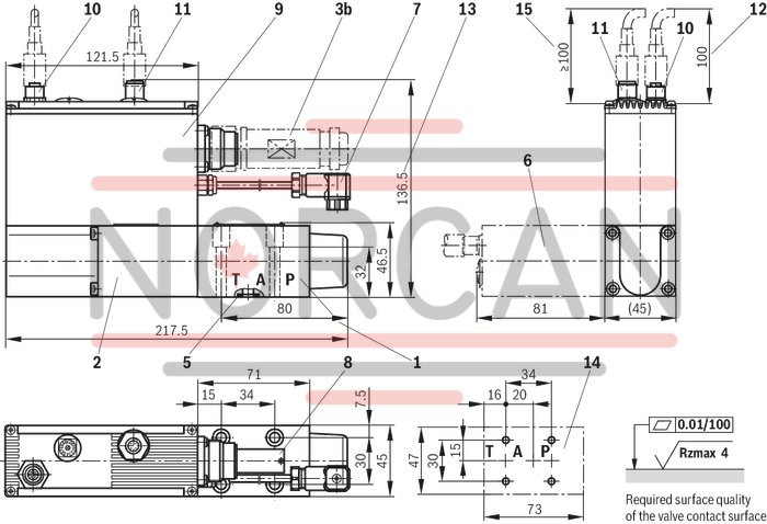
|
1 |
Valve housing |
|
2 |
Proportional solenoid with position transducer |
|
3b |
Mating connector for connector X1 (separate order see Accessories) |
|
5 |
Identical seal rings for ports P, A, and T |
|
6 |
Solenoid rotated by 90° (installation orientation "2") |
|
7 |
Connection swivel angle position sensor (rotary angle sensor VT-SWA-1-1X) |
|
8 |
Name plate |
|
9 |
Integrated electronics |
|
10 |
Mating connector X2 for connection of a pressure transducer HM 16 |
|
11 |
Mating connector X3 for connection of the CAN bus |
|
12 |
Space required for plug-in connection (HM 16) |
|
13 |
Dimension for version VT-DFPC (connection for HM 16 or CAN bus) |
|
14 |
machined valve contact surface |
|
15 |
Space required for CAN connection (plug-in connection on the customer side) |
Valve mounting screws for all types:
4 hexagon socket head cap screws
ISO4762-M6X40-10.9-flZn-240h-L,
friction coefficient μtotal = 0.09 to 0.14 according to VDA 235-101,
Tightening torque MA = 7 Nm,
material number: R913000058
Amending notes on the SY(H)DFE control systems can be found in the operating instructions (see section “Further information about this control system”).