BOSCH REXROTH
R901435685
$2,680.78 USD
- BOSCH REXROTH
- Material:R901435685
- Model:HAB20-330-6X/150G09G-2N111-CE
Quantity in stock: 0
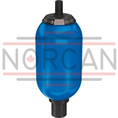
The Bosch Rexroth HAB20-330-6X/150G09G-2N111-CE (R901435685) is a high-quality bladder-type hydraulic accumulator designed for industrial applications that require reliable hydraulic energy storage, emergency energy reserves, and fluid volume compensation. This accumulator has a nominal volume of 330 liters and can withstand a maximum pressure of 330 bar, making it suitable for intermittent operating systems where shock and vibration absorption are critical. The product features a G-threaded working port with radial sealing surface for secure connections and utilizes NBR bladder material suitable for normal temperature ranges, handling both mineral oil and HFC fluids. The Bosch Rexroth accumulator is pre-filled with nitrogen at a specified pressure to ensure optimal performance from the start. It operates efficiently within a temperature range of -20°C to +80°C and conforms to the CE marking under the European Pressure Equipment Directive (EU). The gas port size includes both Gasventil 5/8 UNF and ISO 6149 connections, facilitating easy maintenance or gas pressure adjustments as needed. This model is part of an extensive product group known for its robust design and performance under demanding conditions. Its primary applications include energy storage in systems with intermittent operation, providing an energy reserve during emergencies, compensating for leakage loss, damping shocks and vibrations, as well as flow compensation in response to pressure and temperature fluctuations. For detailed information about the design HABX series and its CE certification applications, users should refer to data sheet RE 50124. The hydraulic accumulator operates based on the principle of gas compressibility versus fluid incompressibility, using a gastight bladder to separate the gas from the fluid section. This ensures that when liquid pressure increases or decreases, the gas volume correspondingly decreases or expands to maintain system equilibrium. The careful construction of this accumulator ensures durability and reliability in various hydraulic system applications.
Bladder-type accumulator size 20 liters, 330 bar for industrial applications at standard temperatures
Bladder-type accumulator in accordance with the European Pressure Equipment Directive 2014/68/EU For hydraulic energy storage in intermittent operating systems. Energy reserve for emergencies. Fluid volume compensation or shock and vibration absorption in hydraulic systems.
Unpacked Weight: 59.5 kg
Applications:
Energy storage in systems with intermittent operation Energy reserve for emergencies Compensation for leakage loss Shock and vibration damping Flow compensation in case of pressure and temperature changes
Refer to data sheet RE 50171 for extensive details about the design HAB-6X and applications with CE certification.
Function, section
General information
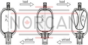
Hydraulic accumulators are hydrostatic devices capable of storing a certain amount of energy in order to release it to the hydraulic system when needed.
Fluids only possess low compressibility; however, gases are highly compressible. The working principle of all gas-loaded hydraulic accumulators is based on this difference.
The difference between bladder and diaphragm type accumulators lies in the type of separator element. Hydraulic accumulators essentially consist of a fluid section and a gas section with a gas-tight separator element.
The fluid section has a connection to the hydraulic circuit.
If a higher liquid pressure is applied to a specific quantity of pressurized gas, the gas volume decreases as the liquid pressure increases, with the gas pressure increasing with the liquid pressure.
If the pressure of the fluid decreases, the fluid is pushed back into the hydraulic system by the expanding gas until the pressure is balanced again.
Bladder-type accumulator
Bladder-type accumulators consist of a seamless cylindrical pressure container (1) made of high-strength steel. An elastic bladder (2) mounted inside the container separates the accumulator into a gas side and a fluid side.
Via the gas valve (4), the bladder is filled with nitrogen up to the intended gas filling pressure p0.
The oil valve (3) located inside the oil port of the bladder-type accumulator closes if the pressure on the gas side is higher compared to the fluid side. This prevents the bladder from entering the oil channel and being destroyed.
When the minimum operating pressure is reached, a small fluid volume (approx. 10% of the hydraulic accumulator's nominal volume) should remain between the bladder and the oil valve in order to prevent the bladder from hitting the valve during each expansion process.
The gas valve (4) consists of sealing cap (4.1), gas valve insert (4.2), gas prefill valve body (4.3), and O-ring (4.4). These parts can be replaced individually.
The type cap (7) includes the technical data and features of the hydraulic accumulator.
Symbol


|
1 |
Containers |
|
2 |
Bladder |
|
3 |
Oil valve |
|
4 |
Gas valve |
|
5 |
Gas valve support |
|
6 |
Nut |
|
7 |
Type cap |
|
8 |
Cover cap |
|
9 |
Protective cap of oil valve |
| Data Sheet | Download Data Sheet |
| 3D CAD | Download 3D CAD |
| Manual | Download Manual |
| Manual | Download Manual |
| Manual | Download Manual |
| Manual | Download Manual |
| Manual | Download Manual |
| Material (diaphragm / bladder) | NBR |
| Max. pressure | 330 |
| Working port type | Pipe thread |
| Working port size | G2 |
| Productgroup ID | 9,10,11,12,13,14 |
| Temperature range | -15….+80°C |
| Conformity description | CE according to directive 2014/68/EU |
| Gas port size | Gasventil 7/8-14 UNF und ISO 4570 8V1 |
| Max. flow | 900 |
| Nominal volume | 20 |
| Weight | 59.5 |
| Conformity | CE |
Ordering code
|
01 |
02 |
03 |
04 |
05 |
06 |
07 |
08 |
09 |
10 |
11 |
12 |
13 |
14 |
|||||
|
HAB |
- |
- |
6X |
/ |
0 |
G |
- |
2 |
1 |
1 |
1 |
- |
|
Device designation |
|||||||||||
|
01 |
Diaphragm type accumulators |
HAB |
|||||||||
|
Nominal capacity |
|||||||||||
|
02 |
1 l |
1 |
|||||||||
|
2,5 l |
2,5 |
||||||||||
|
4 l |
4 |
||||||||||
|
6 l |
6 |
||||||||||
|
10 l |
10 |
||||||||||
|
20 l |
20 |
||||||||||
|
24 l |
24 |
||||||||||
|
32 l |
32 |
||||||||||
|
50 l |
50 |
||||||||||
|
Maximum admissible operating pressure |
|||||||||||
|
03 |
350 bar 1 … 6 l |
350 |
|||||||||
|
330 bar 1 … 50 l |
330 |
||||||||||
|
Component series |
|||||||||||
|
04 |
Component series 60 … 69 (60 … 69: unchanged installation and connection dimensions) |
6X |
|||||||||
|
Gas filling pressure |
|||||||||||
|
05 |
0 bar |
0 |
|||||||||
|
Port size for hydraulic fluid 1) |
|||||||||||
|
06 |
1 |
2.5 |
4 |
6 |
10 |
20 |
24 |
32 |
50 |
||
|
G3/4 |
✔ |
‒ |
‒ |
‒ |
‒ |
‒ |
‒ |
‒ |
‒ |
G05 |
|
|
G1 1/4 |
‒ |
✔ |
✔ |
✔ |
‒ |
‒ |
‒ |
‒ |
‒ |
G07 |
|
|
G2 |
‒ |
‒ |
‒ |
‒ |
✔ |
✔ |
✔ |
✔ |
✔ |
G09 |
|
|
Type of mounting (oil port form) |
|||||||||||
|
07 |
Thread with sealing surface, radial on the inside |
G |
|||||||||
|
Gas port form |
|||||||||||
|
08 |
Gas valve for charging and test device |
2 |
|||||||||
|
Bladder material 1) |
|||||||||||
|
09 |
NBR |
N |
|||||||||
|
ECO |
E |
||||||||||
|
FKM |
F |
||||||||||
|
HNBR |
H |
||||||||||
|
Tank material 1) |
|||||||||||
|
10 |
Steel |
1 |
|||||||||
|
Surface of the tank inside 1) |
|||||||||||
|
11 |
Steel |
1 |
|||||||||
|
Surface of the connection side 1) |
|||||||||||
|
12 |
Steel |
1 |
|||||||||
|
Certification acceptance |
|||||||||||
|
13 |
CE (DGRL 2014/68/EU) |
CE |
|||||||||
|
Instructions for use |
BA |
||||||||||
|
14 |
Further details in the plain text e. g. SO variant |
* |
|||||||||
general
|
Nominal capacity |
l |
1 | 2.5 | 4 | 6 | 10 | 20 | 24 | 32 | 50 |
|
Weight |
kg |
7 | 10 | 16.5 | 20 | 32 | 53 | 61 | 85 | 123 |
|
Design |
Bladder-type accumulators | |||||||||
|
Installation position |
Bottom fluid connection socket, others upon request | |||||||||
|
Mounting type |
With clamping collars and console | |||||||||
|
Line connection |
Screw-in thread | |||||||||
hydraulic
|
Nominal capacity |
VNenn |
l |
1 | 2.5 | 4 | 6 | 10 | 20 | 24 | 32 | 50 |
|
Effective gas volume |
Veff |
l |
1 | 2.4 | 3.7 | 5.9 | 9.2 | 18.1 | 24.5 | 33.4 | 48.7 |
|
Maximum flow |
qmax |
l/min |
240 | 450 | 450 | 450 | 900 | 900 | 900 | 900 | 900 |
|
Maximum operating pressure |
pmax |
bar |
330 | 330 | 330 | 330 | 330 | 330 | 330 | 330 | 330 |
|
bar |
350 | 350 | 350 | 350 | - | - | - | - | - | ||
|
Maximum admissible pressure fluctuation range |
Δpdyn |
bar |
200 | 200 | 200 | 200 | 125 | 125 | 125 | 125 | 125 |
|
Hydraulic fluid 1) |
Hydraulic oil according to DIN 51524 | ||||||||||
|
Hydraulic fluid temperature range |
NBR |
°C |
-15 … +80 1) | ||||||||
|
ECO |
°C |
-32 … +80 | |||||||||
|
FKM |
°C |
-20 … +80 | |||||||||
|
HNBR |
°C |
-30 … +80 | |||||||||
| 1) | Other hydraulic fluids upon request. |
pneumatic
|
Charging gas |
Nitrogen, cleanliness class 4.0, N2 = 99.99 vol. % | ||
|
Gas filling pressure |
p0 |
bar |
0 |
|
Hydraulic fluids |
Material |
|
Mineral oils |
NBR |
|
ECO |
|
|
HNBR |
|
|
HFC |
NBR |
|
HFD |
FKM |
| NBR ‒ Acrylonitrile-butadiene rubber | |
| ECO ‒ Epichlorohydrin rubber | |
| HNBR ‒ Hydrated acrylonitrile butadiene rubber | |
| FKM ‒ Fluorocarbon rubber |
For applications outside these parameters, please consult us!
Calculation
Pressures
The following pressures are of decisive importance for the calculation of an accumulator:
p0 Gas filling pressure at room temperature and empty fluid chamber
p0 (t) Gas filling pressure at operating temperature
p0 (tmax) Gas filling pressure at maximum operating temperature
p1 Minimum operating pressure
p2 Maximum operating pressure
In order to achieve the best utilization of the accumulator volume possible as well as a long life cycle, compliance with the following values is recommended:
p0 (tmax) ~ 0.9 × p1 (1)
The highest hydraulic pressure should not exceed four times the filling pressure, as otherwise too much stress will be put on the elasticity of the bladder, resulting in too great a compression change with strong gas heating:
p2 ≦ 4 × p0 (2)
The life cycle of the accumulator bladder is the higher the smaller the difference between p1 and p2 is. However, the operating ratio of the maximum accumulator capacity will also be reduced accordingly.
Oil volume
According to the pressures p0 … p2, the gas volumes V0 … V2 will result.
In this process, V0 simultaneously is the nominal volume of the accumulator.
The available oil volume ΔV corresponds to the difference of the gas volumes V1 and V2:
ΔV ≦ V1 – V2 (3)
The gas volume variable within a pressure differential is determined by the following equations:
For an isothermal state change of gases, i.e. when the change of the gas cushion happens so slowly as to leave sufficient time for a complete thermal exchange between the nitrogen and its environment, therefore keeping the temperature constant, the following applies:p0 × V0 = p1 × V1 = p2 × V2 (4.1) For an adiabatic state change, i.e. a quick change of the gas cushion accompanied by a temperature change of the nitrogen, the following applies:p0 × Vχ0 = p1 × Vχ1 = p2 × Vχ2 (4.2)
χ = ratio of the specific gas heats (adiabatic exponent), for nitrogen = 1.4
In practice, state changes rather follow adiabatic laws. Often charging is isothermal and discharge is adiabatic.
Considering the equations (1) and (2), ΔV is between 50% and 70% of the nominal accumulator volume. The following applies as a guiding principle:
V0 = 1.5 … 3 × ΔV (5)
Calculation diagram
For graphic determination, the formulas (4.1) and (4.2) are converted into diagrams. Depending on the task, the available oil volume, the accumulator size or the pressures can be determined.
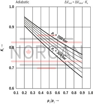
Correction factor Ki and Ka
The equations (4.1) and (4.2) apply to ideal gases only.
The behavior of real gases, however, will show considerable variation at operating pressures above 200 bar which will have to be accounted for by correction factors. These can be taken from the following diagrams.
The correction factors the ideal sampling volume ΔV is to be multiplied with lie within a range of 0.6 … 1.
Application of the calculation diagrams
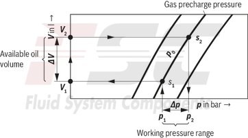
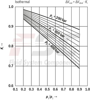
Isothermal state changes p0 = 1 … 90 bar
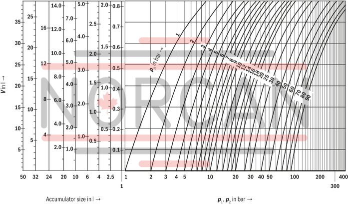
Isothermal state changes p0 = 100 … 300 bar
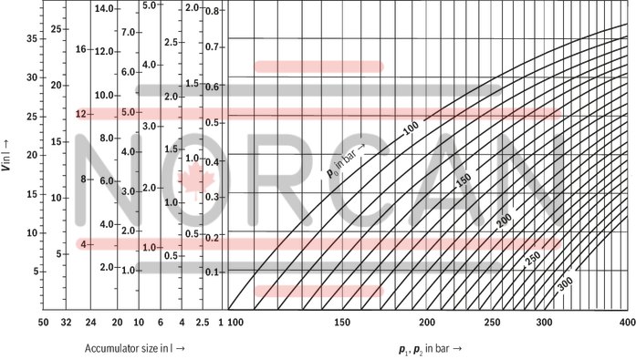
Adiabatic state changes p0 = 1 … 90 bar
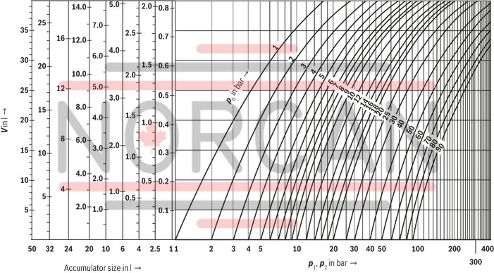
Adiabatic state changes p0 = 100 … 300 bar
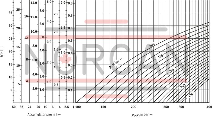
Applications
Various applications exist for hydro-pneumatic accumulators:
▶ Energy storage in order to save pump drive power in intermittent operation systems.
▶ Energy reserve for emergencies, e.g. upon failure of the hydraulic pump.
▶ Compensation of leakage losses.
▶ Impact and vibration absorption in case of periodic vibrations.
▶ Volume compensation in case of pressure and temperature changes.
Mode of operation
Fluids are almost incompressible and therefore cannot store pressure energy. Hydro-pneumatic Rexroth accumulators use the compressibility of a gas for fluid storage. Exclusively use nitrogen of cleanliness class 4.0!
N2 = 99.99 vol. %
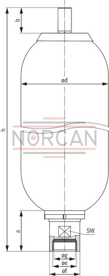
Dimensions in mm
|
Nominal capacity |
Ordering code/type |
h |
Ød |
a |
b |
Øe |
Øf |
Øg |
SW |
Weight |
|||
|
l |
mm |
mm |
mm |
mm |
mm |
mm |
mm |
kg |
|||||
| 1 | HAB1-330-6X/...G05G... | 320.5 ‒ 354.5 | 112.5 ‒ 115.5 | 65 | ± 3 mm | 715 |
± 3 mm - |
G3/4 | 52.4 | 23 |
H7 |
50 | 7 |
| HAB1-350-6X/...G05G... | 320.5 ‒ 354.5 | 112.5 ‒ 115.5 | 65 | ± 3 mm | 715 |
± 3 mm - |
G3/4 | 52.4 | 23 |
H7 |
50 | 7 | |
| 2.5 | HAB2,5-330-6X/...G07G... | 520.5 ‒ 562.5 | 112.5 ‒ 115.5 | 65 | ± 3 mm | 715 |
± 3 mm - |
G1 1/4 | 52.4 | 36 |
H8 |
50 | 10 |
| HAB2,5-350-6X/...G07G... | 520.5 ‒ 562.5 | 112.5 ‒ 115.5 | 65 | ± 3 mm | 715 |
± 3 mm - |
G1 1/4 | 52.4 | 36 |
H8 |
50 | 10 | |
| 4 | HAB4-330-6X/...G07G... | 400.5 ‒ 442.5 | 166.3 ‒ 169.7 | 65 | ± 3 mm | 715 |
± 3 mm - |
G1 1/4 | 52.4 | 36 |
H8 |
50 | 16.5 |
| HAB4-350-6X/...G07G... | 400.5 ‒ 442.5 | 166.3 ‒ 169.7 | 65 | ± 3 mm | 715 |
± 3 mm - |
G1 1/4 | 52.4 | 36 |
H8 |
50 | 16.5 | |
| 6 | HAB6-330-6X/...G07G... | 535.5 ‒ 569.5 | 166.3 ‒ 169.7 | 65 | ± 3 mm | 715 |
± 3 mm - |
G1 1/4 | 52.4 | 36 |
H8 |
50 | 20 |
| HAB6-350-6X/...G07G... | 535.5 ‒ 569.5 | 166.3 ‒ 169.7 | 65 | ± 3 mm | 715 |
± 3 mm - |
G1 1/4 | 52.4 | 36 |
H8 |
50 | 20 | |
| 10 | HAB10-330-6X/...G09G... | 559 ‒ 591 | 216.8 ‒ 221.2 | 101.5 | ± 3 mm | 715 |
± 3 mm - |
G2 | 76 | 54 |
H7 |
70 | 32 |
| 20 | HAB20-330-6X/...G09G... | 869 ‒ 901 | 216.8 ‒ 221.2 | 101.5 | ± 3 mm | 715 |
± 3 mm - |
G2 | 76 | 54 |
H7 |
70 | 53 |
| 24 | HAB24-330-6X/...G09G... | 1,004 ‒ 1,036 | 216.8 ‒ 221.2 | 101.5 | ± 3 mm | 715 |
± 3 mm - |
G2 | 76 | 54 |
H7 |
70 | 61 |
| 32 | HAB32-330-6X/...G09G... | 1,389 ‒ 1,421 | 216.8 ‒ 221.2 | 101.5 | ± 3 mm | 715 |
± 3 mm - |
G2 | 76 | 54 |
H7 |
70 | 85 |
| 50 | HAB50-330-6X/...G09G... | 1,904 ‒ 1,936 | 216.8 ‒ 221.2 | 101.5 | ± 3 mm | 715 |
± 3 mm - |
G2 | 76 | 54 |
H7 |
70 | 123 |
Project planning information
Bladder-type accumulators have to be safely and permanently fastened to the machine or system using mounting elements. The fastening is intended to keep the oil port tension-free. Particularly, no tension forces or static or dynamic inertia forces should be applied to the oil port.
Thermal expansion of the supporting structure and vibrations originating from the environment should be considered in the selection of suitable mounting points.
HAB mounting elements
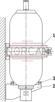
|
1 |
Clamp |
|
2 |
Console |
|
3 |
Rubber support ring |
|
Clamp type |
Material number |
Accumulator size |
|||||
|
1 |
4 |
|
20 |
|
|||
|
2,5 |
6 |
10 |
24 |
|
|||
|
|
|
|
35 |
50 |
|||
|
Clamp |
110-120 |
1531316021 |
1 |
||||
|
Clamp |
160-170 |
1531316022 |
2 |
||||
|
Clamp |
218-228 |
1531316026 |
1 |
2 |
|||
|
Clamp |
224-230 |
1531316005 |
2 |
||||
|
Console |
1531334008 |
1 |
1 |
1 |
|||
|
Rubber support ring |
1530221042 |
1 |
1 |
1 |
|||
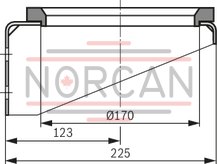
Console and rubber support ring
Console (material number: 1531334008)
Dimensions in mm
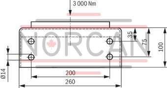
Rubber support ring (material number: 1530221042)
Dimensions in mm
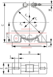
Mounting clamps
Type F1
Dimensions in mm
Mounting clamps
Type F2
Dimensions in mm
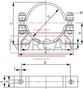
|
Clamp type |
A |
B |
C |
⌀D |
E |
H |
K |
M |
S |
Material number |
|
|
mm |
mm |
mm |
mm |
mm |
mm |
mm |
mm |
||||
| Clamp | 110-120 F1 | 135 | 96 | 150 | 110 ‒ 120 | 50 | 64 ‒ 69 | - | M8 | 3 | 1531316021 |
| Clamp | 160-170 F1 | 237 | 147 | 200 | 160 ‒ 170 | 50 | 90 ‒ 95 | - | M8 | 4 | 1531316022 |
| Clamp | 218-228 F1 | 237 | 147 | 258 | 218 ‒ 228 | 50 | 120 ‒ 125 | - | M8 | 4 | 1531316026 |
| Clamp | 224-230 F2 | 254 | 212 | 244 | 224 ‒ 230 | 50 | 120 ‒ 123 | 295 | M12 | 3 | 1531316005 |
Charging and test device

|
Test case |
Material number |
|
for bladder-type accumulator (HAB) |
0538103011 |
|
Case (wihout contents) |
R901079781 |
|
Charging and test valve HAB |
0538103005 |
|
Pressure gauge 0 … 250 bar |
1537231001 |
|
Hose l = 2.5 m with adapter piece form "D" |
1530712005 |
|
for bladder and diaphragm accumulator (HAB/HAD) |
0538103014 |
|
Components as above plus filling and test valve HAD |
0538103006 |
|
Accessory parts to be ordered separately |
Material number |
|
Pressure gauge 0 … 25 bar |
R900033955 |
|
Pressure gauge 0 … 60 bar |
1537231002 |
|
Pressure gauge 0 … 400 bar |
1537231005 |
|
Adapter piece |
|
|
Form "F" |
1533391010 |
|
Form "GB" |
1533391011 |
|
Form "USA" |
1533391012 |
|
Form "KR" |
1533391013 |
|
Form "J" |
1533391014 |
|
Form "RUS" |
1533391015 |
|
Hose l = 5 m with transition socket form “D” |
1530712006 |
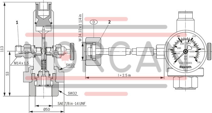
Dimensions of charging and test valve
1 valve body with check valve, discharge valve, pressure gauge connection, and gas hose connection.
Dimensions in mm
|
1 |
Spare part, Material no. 1 537 410 065 |
|
2 |
Adapter see "Adapter from nitrogen bottle..." |
Adapter for nitrogen bottle to cap nut
Dimensions in mm
Material no. 1533391010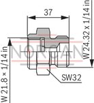
|
Material no. 1533391013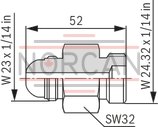
|
Material no. R900034782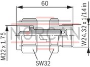
|
Material no. 1533391011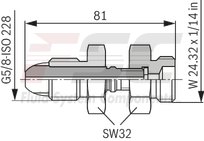
|
Material no. R900216133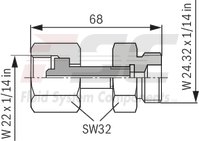
|
Material no. R900708208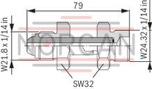
|
Material no. 1533391012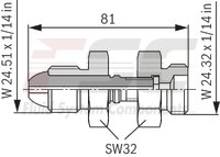
|
Material no. 1533391015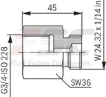
|
Material no. R901070776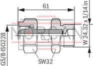
|
|
Country |
Material number |
||||||||
|
1533391010 |
1533391011 |
1533391012 |
1533391013 |
R900216133 |
1533391015 |
R900034782 |
R900708208 |
R901070776 |
|
|
Brazil |
x |
||||||||
|
Bulgaria |
x |
||||||||
|
China |
x |
||||||||
|
France |
x |
||||||||
|
Greece |
x |
||||||||
|
Great Britain |
x |
||||||||
|
India |
x |
||||||||
|
Italy |
x |
||||||||
|
Japan |
x |
||||||||
|
Canada |
x |
||||||||
|
Korea North |
x |
||||||||
|
Korea South |
x |
||||||||
|
Malaysia |
x |
||||||||
|
Mexico |
x |
||||||||
|
Romania |
x |
||||||||
|
Russia |
x |
||||||||
|
Spain |
x |
||||||||
|
Saudi Arabia |
x |
||||||||
|
Singapore |
x |
||||||||
|
Taiwan |
x |
||||||||
|
Turkey |
x |
||||||||
|
USA |
x |
||||||||
|
Other countries on request. |
|||||||||
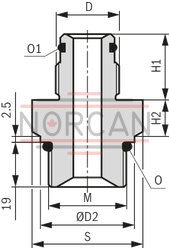
Accumulator adapter for accumulator shut-off blocks type ABZSS
Please select the matching type according to data sheet 50131.
Fig. 2
Dimensions in mm
|
Accumulator shut-off block |
Accumulator type |
Accumulator DN |
Accumulator adapter |
D |
ØD2 |
H1 |
H2 |
M |
O |
O1 |
S |
||||||
|
ABZSS10, ABZSS20 |
ABZSS08 |
ABZSS10, ABZSS20 |
ABZSS08 |
ABZSS10, ABZSS20 |
ABZSS08 |
ABZSS10, ABZSS20 |
ABZSS08 |
ABZSS10, ABZSS20 |
ABZSS08 |
ABZSS10, ABZSS20 |
ABZSS08 |
||||||
|
mm |
mm |
mm |
mm |
mm |
mm |
||||||||||||
|
ABZSS08 ABZSS10 ABZSS20 |
Bladder-type accumulator Data sheet 50171 | 1 | S10 | S105 | G3/4A | 39.9 | 35 | 28 | 15.5 | 15.5 | M33 x 2 | M20 x 1.5 | 29.7 x 2.8 | 24 x 2 | 18 x 2.5 | SW41 | SW36 |
| 2.5 | S12 | S107 | G1 1/4A | 37 | 16.5 | 17.5 | 30 x 3 | SW46 | SW46 | ||||||||
| 4 | |||||||||||||||||
| 6 | |||||||||||||||||
| 10 | S13 | S109 | G2A | 43 | 20.5 | 18.5 | 48 x 3 | SW65 | SW65 | ||||||||
| 20 | |||||||||||||||||
| 35 | |||||||||||||||||
| 50 | |||||||||||||||||
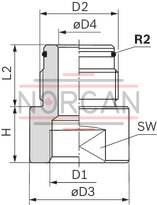
Adapter to metric thread
(HAB..–1X to HAB..–4X and –6X)Dimensions in mm
|
Nominal capacity |
ISO 228 |
H |
L2 |
ØD3 |
ØD4 |
SW |
|||||
|
D2 |
MA |
D1 |
MA |
||||||||
|
l |
Nm |
Tolerance Nm |
Nm |
Tolerance Nm |
mm |
mm |
mm |
mm |
mm |
||
| 1 | G3/4 | 180 |
+ 18 0 |
M30 x 1.5 | 180 |
+ 18 0 |
32 | 28 | 46 | 12 | 41 |
| 2.5 ... 6 | G1/14 | 450 |
+ 45 0 |
M40 x 1.5 | 400 |
+ 40 0 |
43 | 37 | 60 | 20 | 55 |
| 10 ... 50 | G2 | 500 |
+ 50 0 |
M50 x 1.5 | 450 |
+ 45 0 |
41 | 44 | 78 | 32 | 70 |
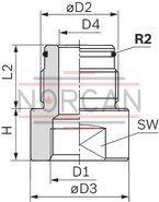
Adapter for reduction of pipe connection
Dimensions in mm
|
Nominal capacity |
ISO 228 |
H |
L2 |
ØD3 |
ØD4 |
SW |
|||||
|
D2 |
MA |
D1 |
MA |
||||||||
|
l |
Nm |
Tolerance Nm |
Nm |
Tolerance Nm |
mm |
mm |
mm |
mm |
mm |
||
| 1 | G3/4 | 180 |
+ 18 0 |
G3/8 | 70 |
+ 7 0 |
8 | 28 | 38 | 12 | 32 |
| 2.5 ... 6 | G1/14 | 450 |
+ 45 0 |
G1/2 | 115 |
+ 12 0 |
8 | 37 | 60 | 24 | 55 |
| 2.5 ... 6 | G1/14 | 450 |
+ 45 0 |
G3/4 | 180 |
+ 18 0 |
8 | 37 | 60 | 24 | 55 |
| 10 ... 50 | G2 | 500 |
+ 50 0 |
G1/2 | 115 |
+ 12 0 |
20 | 44 | 75 | 30 | 65 |
| 10 ... 50 | G2 | 500 |
+ 50 0 |
G3/4 | 180 |
+ 18 0 |
20 | 44 | 75 | 30 | 65 |
| 10 ... 50 | G2 | 500 |
+ 50 0 |
- | 310 |
+ 31 0 |
20 | 44 | 75 | 30 | 65 |
| 10 ... 50 | G2 | 500 |
+ 50 0 |
G1 1/2 | 450 |
+ 45 0 |
40 | 44 | 75 | 32 | 65 |
Pressure monitoring
Adapter for pressure gauge, material number 1535400171
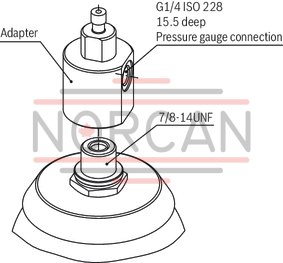
Gas valve

|
Spare part kit for gas valve |
Material number R901438300 |
|
|
Components |
Quantity |
|
|
1 |
Protective cap |
1 |
|
2 |
Sealing cap series 60 |
1 |
|
3 |
Valve insert series 60 |
1 |
|
4 |
Gas valve series 60 |
1 |
|
5 |
O-ring |
1 |
|
6 |
Nut |
1 |
Spare parts
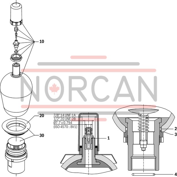
Seal kit (position 1 … 4)
|
Accumulator size |
Material number |
Material number |
|
NBR, HNBR, ECO |
FKM |
|
|
l |
||
| 1 | R901441920 | - |
| 2.5 ... 6 | R901441921 | - |
| 10 ... 50 | R901441922 | R901441923 |
|
Accumulator size |
10 Spare bladder with gas valve and seal kit |
20 Holding ring |
30 Oil valve kit consisting of holding ring and oil valve |
||||
|
Material number |
Material number |
||||||
|
NBR |
ECO |
FKM |
HNBR |
NBR, HNBR, ECO |
FKM |
|
|
|
l |
|||||||
| 1 | R901437540 | - | - | R901438250 | R901438280 | R901438290 | - |
| 2.5 | R901437541 | - | - | R901438251 | R901438280 | R901438290 | - |
| 4 | R901437542 | R901438234 | - | R901438252 | R901438280 | R901438290 | R901438270 |
| 6 | R901437543 | - | - | R901438253 | R901438280 | R901438290 | R901438270 |
| 10 | R901437544 | R901438235 | R901438240 | R901438254 | R901438281 | R901438291 | R901438271 |
| 20 | R901437545 | - | R901438241 | R901438255 | R901438281 | R901438291 | R901438271 |
| 24 | R901437546 | - | - | R901438256 | R901438281 | R901438291 | R901438271 |
| 32 | R901437547 | R901438236 | R901438242 | R901438257 | R901438281 | R901438291 | R901438271 |
| 50 | R901437548 | - | R901438243 | R901438258 | R901438281 | R901438291 | R901438271 |
Important notices
Intended use
Rexroth bladder-type accumulators type HAB..-6X are intended for the set-up of hydraulic drive systems in stationary mechanical engineering and plant construction.
In mobile applications or applications in which acceleration forces are applied to the bladder-type accumulator during intended use, its use is permitted only following release by the competent Rexroth product manager. Please contact technical sales for this.
Rexroth bladder-type accumulators type HAB..-6X are not intended for private use.
Safety instructions for hydraulic accumulators
For the hydraulic accumulator type HAB..-6X, observe the operating instructions 50171-B. The machine end-user will have sole responsibility for compliance.
General notices for hydraulic accumulators in hydraulic system can be found in ISO 4413.
Keep all documents included in the delivery in a safe place; they will be required by the expert in recurring tests.
Legal provisions
Hydraulic accumulators are pressure vessels and subject to the application national provisions and/or regulations valid at the place of installation.
In Germany, the Ordinance on Industrial Safety and Health (BetrSichV) applies.
Special regulations are to be observed in shipbuilding, aircraft construction, mining, etc.
Authorized persons
According to Ordinance on Industrial Safety and Health (BetrSichV), only authorized persons may carry out tests.
Authorized persons are such persons having obtained the required expert knowledge through professional training, experience and recent professional activity.
Safety equipment
Notice:
Hydraulic accumulators have to be secured against operation outside of the admissible limits according to Pressure Equipment Directive 2014/68/EU.
In order not to exceed the maximum operating pressure, we recommend the use of an accumulator shut-off block type ABZSS according to data sheet 50131.

